
Telescopic cover and machine tool
Patent Information
- Authority / Receiving Office
- US · United States
- Current Assignee / Owner
- Publication Date
- 2019-01-17
Smart Images
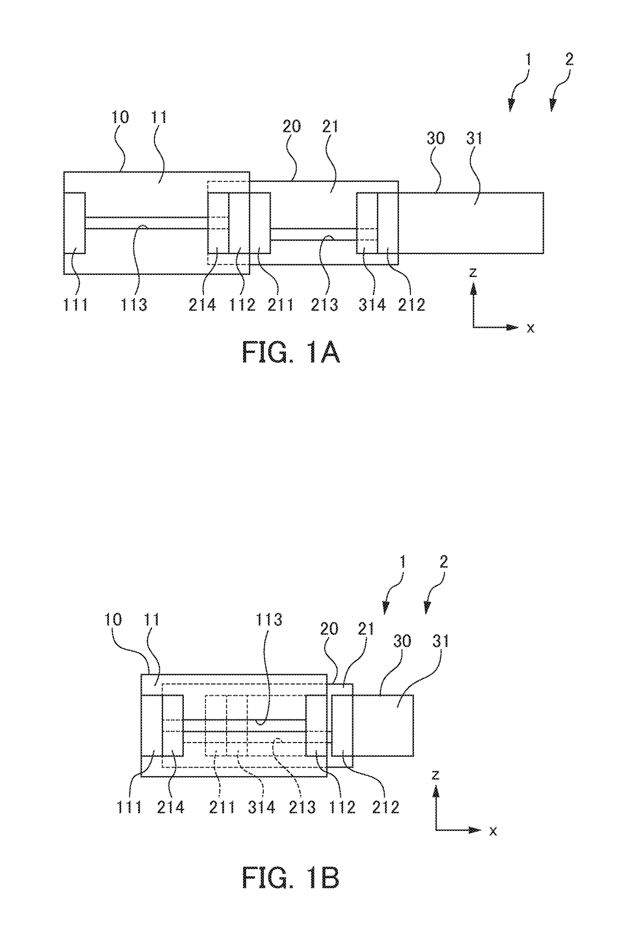
Figure 1 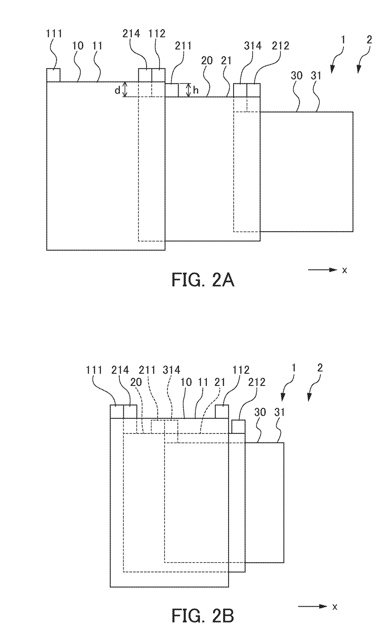
Figure 2
Abstract
Description
[0001] This application is based on and claims the benefit of priority from Japanese Patent Application No. 2017-137892, filed on 14 Jul. 2017, the content of which is incorporated herein by reference.BACKGROUND OF THE INVENTIONField of the Invention
[0002] The present invention relates to a telescopic cover formed to be freely expandable and contractible, and a machine tool including the telescopic cover.Related Art
[0003] In conventional machine tools, a cover generally called a telescopic cover that expands and contracts at the time of axis movement is used, since a drive unit needs to be protected from chips and cutting fluid, and in order to suppress a size of the machine tool. This telescopic cover is formed by sequentially overlapping a plurality of tube-shaped cover pieces having different sizes in a nesting structure with each other so that the entire telescopic cover is freely expandable and contractible in a direction of the nesting structure.
[0004] For example, telescopic cove...
Examples
Embodiment Construction
[0018]An embodiment of the present invention will be described in detail below with reference to FIG. 1A, FIG. 1B, FIG. 2A, and FIG. 2B. FIG. 1A is a side view showing a state in which a telescopic cover 2 of a machine tool 1 according to an embodiment of the present invention is expanded. FIG. 1B is a side view showing a state in which the telescopic cover 2 shown in FIG. 1A is contracted. FIG. 2A is a plan view showing a state in which the telescopic cover 2 shown in FIG. 1A is expanded. FIG. 2B is a plan view showing a state in which the telescopic cover 2 shown in FIG. 1A is contracted.
[0019]As shown in FIG. 1, the telescopic cover 2 of the machine tool 1 is formed to be freely expandable and contractible in a predetermined direction X by overlapping a plurality of rectangular tube-shaped cover pieces 10, 20, 30 having different sizes in a nesting structure with each other. The predetermined direction X is a center axis direction of the rectangular tube-shaped cover pieces 10, 2...