
Extracting device of molded article
Patent Information
- Authority / Receiving Office
- US · United States
- Current Assignee / Owner
- Publication Date
- 2005-12-15
- Estimated Expiration
- Not applicable · inactive patent
Smart Images
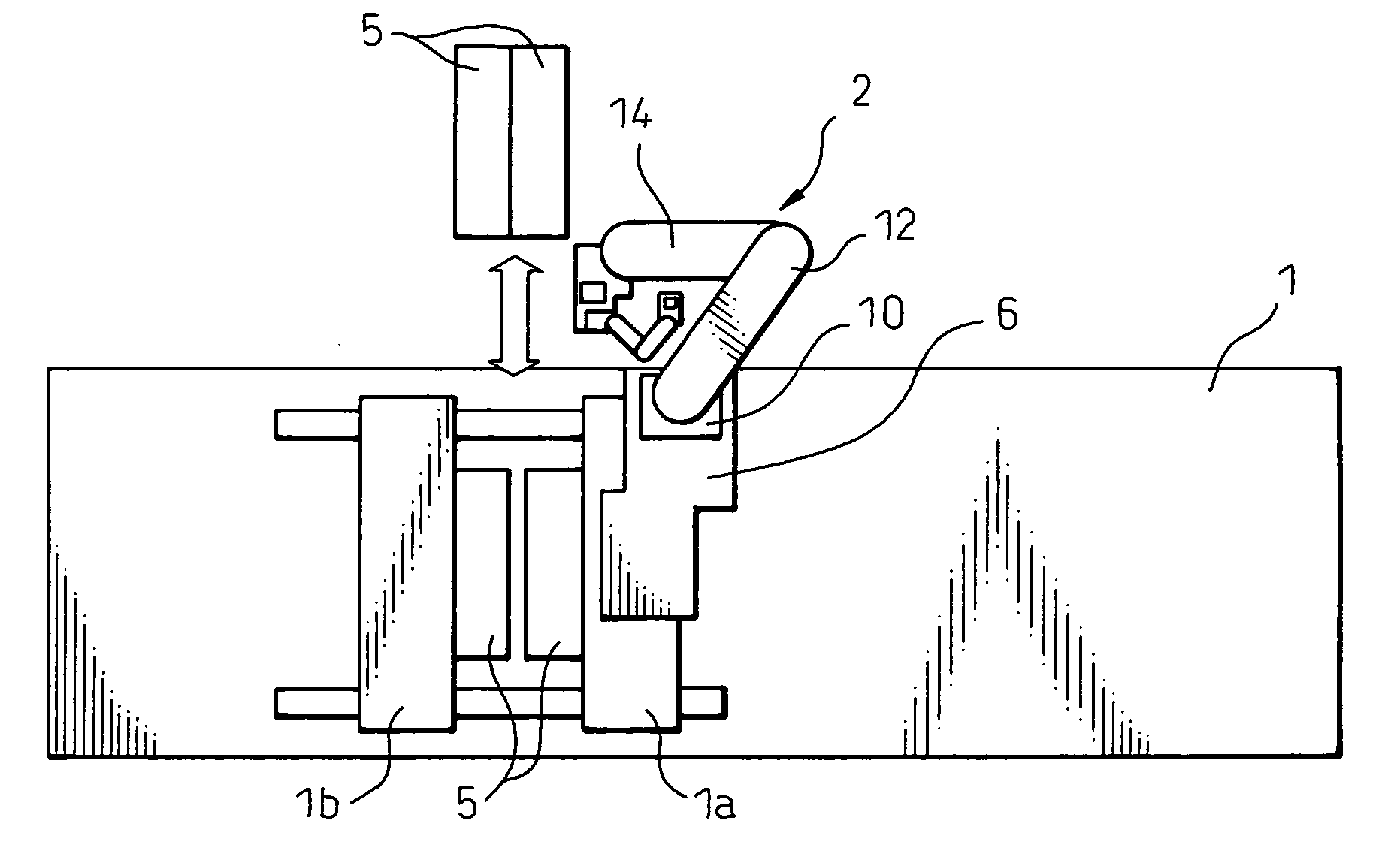
Figure 1 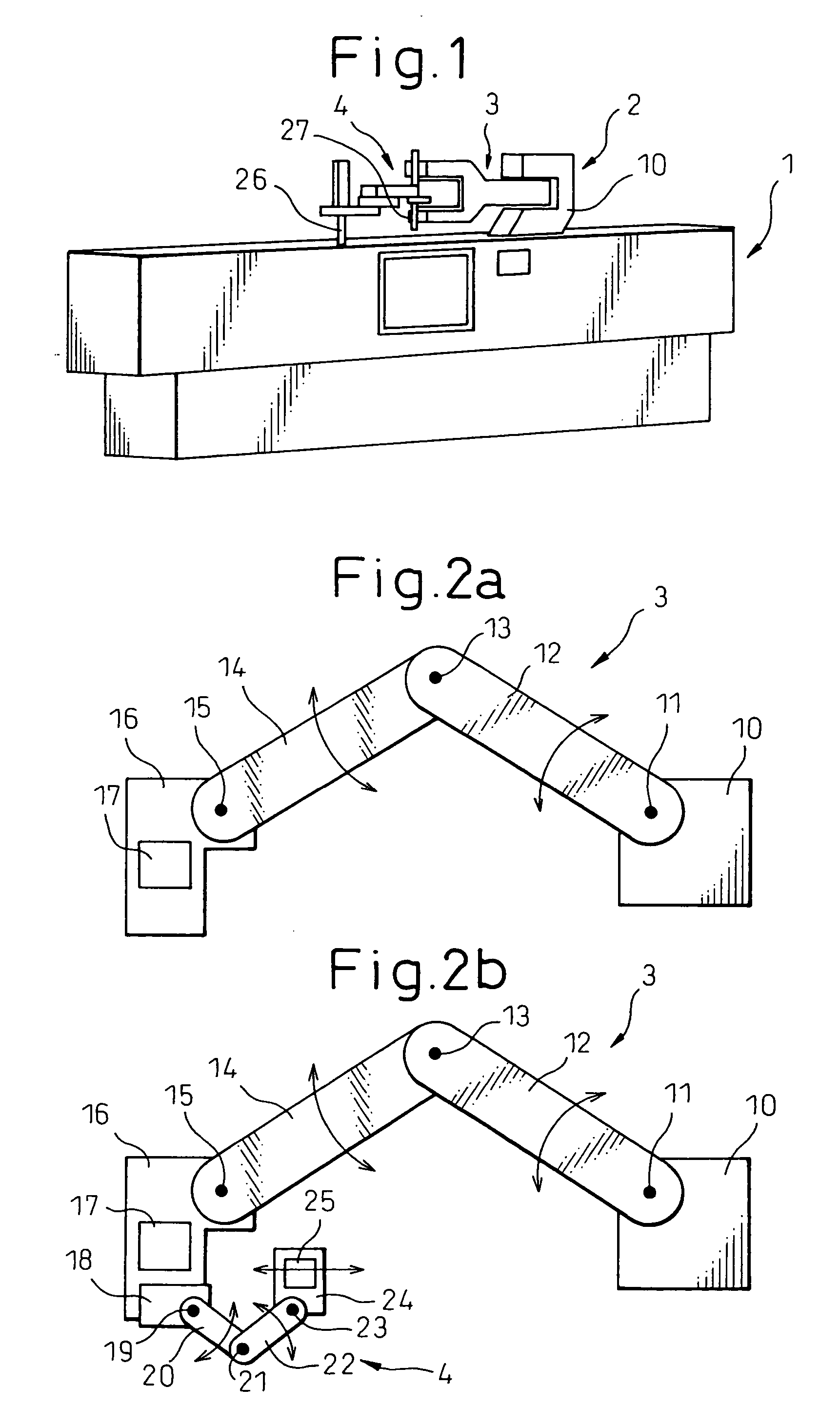
Figure 2 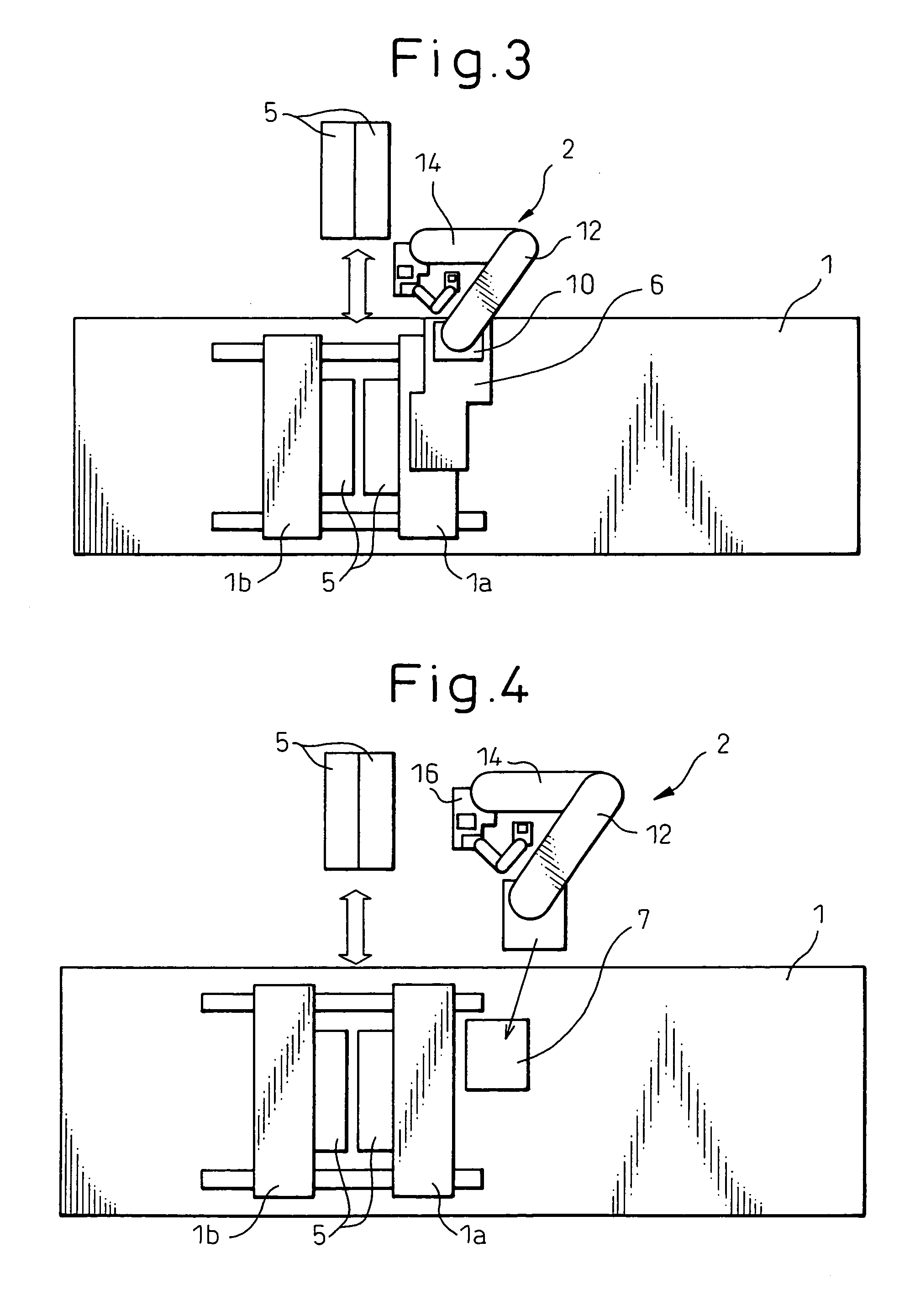
Figure 3
Abstract
Description
BACKGROUND OF THE INVENTION
[0001] 1. Field of the Invention
[0002] The present invention relates to an extracting device, loaded on a molding machine, for extracting a molded article when a mold of the machine is unclamped.
[0003] 2. Description of the Related Art
[0004] An extracting device is arranged with a molding machine, in order to extract a molded article, positioned in an opened or unclamped mold, and a runner after the molded article is formed in the molding machine. In general, this extracting device is type of a rectangular coordinate system including a plurality of straight axes.
[0005] FIG. 5 shows an example of an extracting device of the rectangular coordinate system type, mounted on a molding machine 1. A stationary base 101 of the extracting device 100 of the rectangular coordinate system type is attached to the molding machine 1. The stationary base 101 has a guide means for guiding a movable member 102 in the X-axis direction perpendicular to the longitudinal dir...
Examples
Embodiment Construction
[0024] One embodiment of the present invention is explained below with reference to drawings.
[0025]FIG. 1 is a schematic perspective view of an extracting device 2 for a molded article, loaded on a molding machine 1. The extracting device 2 is mounted on an upper part of a mold fixing member fixed to a frame of the molding machine 1. The extracting device of the embodiment is constituted by a first unit 3 for driving a first vertical motion arm and a second unit 4 detachably mounted to the end of the first unit 3.
[0026]FIG. 2a is an explanatory view of an arm constitution of the extracting device 2. A stationary base 10 is configured to connect the extracting device 2 to the molding machine 1. A first arm 12 has one end mounted to the stationary base 10 such that the first arm 12 is rotatable about a generally vertical first axis 11. A second arm 14 has one end mounted to another end of the first arm 12 such that the second arm 14 is rotatable about a second axis 13 generally para...