
Parking guidance camera apparatus and method of installing the same
Patent Information
- Authority / Receiving Office
- US · United States
- Current Assignee / Owner
- Publication Date
- 2019-09-26
Smart Images
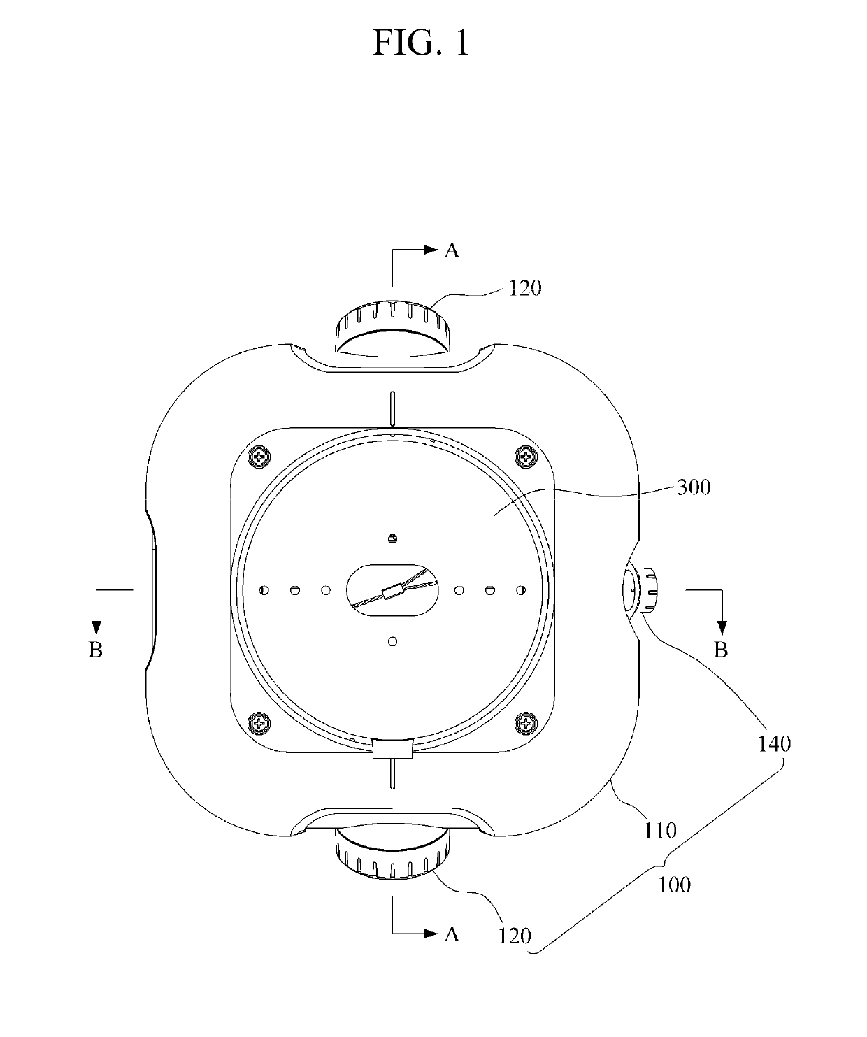
Figure 1 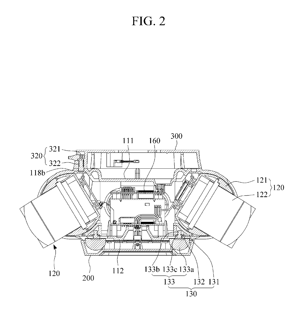
Figure 2 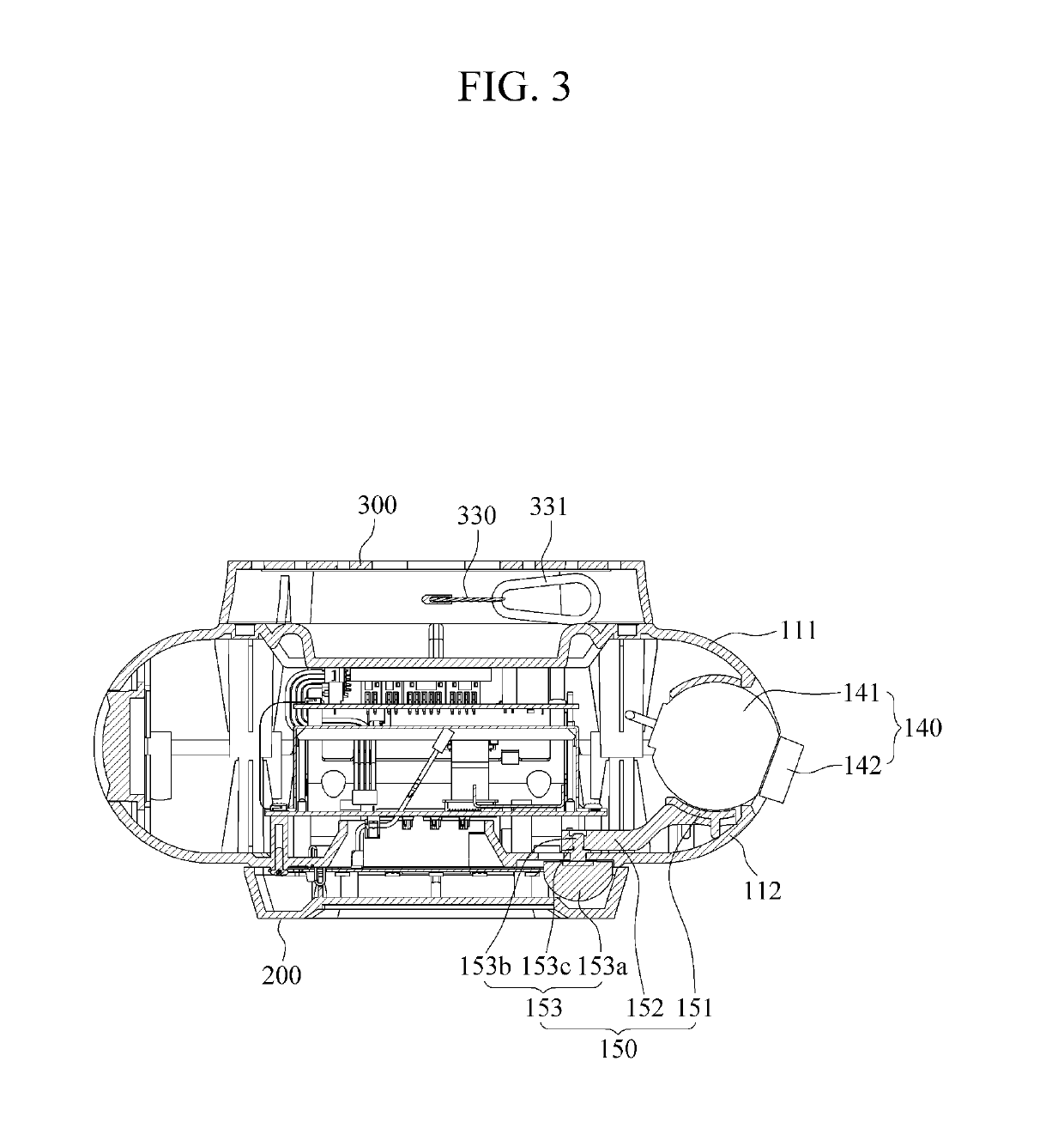
Figure 3
Abstract
Description
CROSS-REFERENCE TO RELATED APPLICATION
[0001] This application claims priority to and the benefit of Korean Registered Patent No. 10-2018-0033392, filed on Mar. 22, 2018, and Korean Registered Patent No. 10-2018-0033393, filed on Mar. 22, 2018, the disclosure of which is incorporated herein by reference in its entirety.BACKGROUND1. Field
[0002] The present disclosure relates to a camera apparatus, and more specifically, to a camera apparatus used for parking guidance.2. Description of Related Art
[0003] Since the number of vehicles is increasing, a shortage of parking spaces is becoming a social issue. Particularly, a large building such as a department store, a superstore, an apartment, a hospital, or the like in which a plurality of vehicles frequently enter and exit has a problem with parking spaces even despite often having a multilayer parking space.
[0004] A large parking lot is formed of a plurality of parking surfaces (parking blocks) and a passage, and a driver can be inconvenience...
Examples
Embodiment Construction
[0024]The present disclosure will be described below in detail with reference to the accompanying drawings. Here, the same reference numerals are used for the same components in the description, and repeated descriptions and a detailed description for known functions and configurations which may unnecessarily obscure the spirit of the present disclosure will be omitted. Embodiments of the present disclosure are provided to more completely describe the present disclosure to those skilled in the art. Accordingly, a shape, a size and the like of elements in the drawings may be exaggerated for more clear description.
[0025]FIG. 1 is a plan view of a parking guidance camera apparatus according to an embodiment of the present disclosure. FIG. 2 is a cross-sectional view cut along line A-A in FIG. 1. FIG. 3 is a cross-sectional view cut along line B-B in FIG. 1. FIG. 4 is an exploded perspective view of FIG. 1. FIG. 5 is an enlarged perspective view of area C in FIG. 4. FIG. 6 is a bottom v...