

Local reinforcement of injection moldings
Patent Information
- Authority / Receiving Office
- US · United States
- Current Assignee / Owner
- Publication Date
- 2019-10-03
- Estimated Expiration
- Not applicable · inactive patent
Smart Images
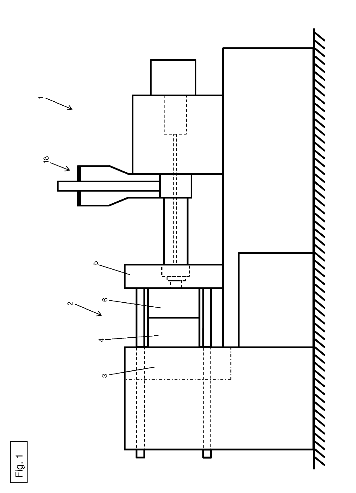
Figure 1 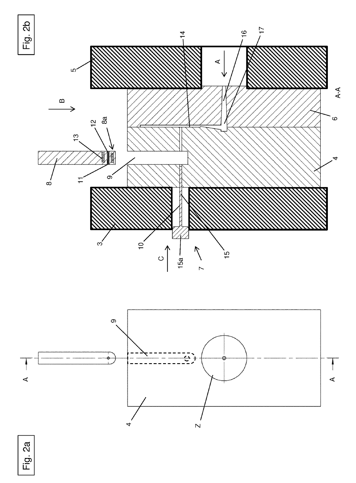
Figure 2 
Figure 3
Abstract
Description
[0001] The present invention relates to a method for using an injection mold for manufacturing plastic components, in particular components of power tools, the injection mold containing at least one sprue plate, a push-in device and an ejector plate, and at least one cavity being provided between the sprue plate and the ejector plate when the sprue plate and the ejector plate are in an assembled state, and the ejector plate containing at least one fiber channel, through which at least one fiber bundle having a thermoplastic matrix is transportable to the cavity, with the aid of the push-in device, along at least part of the sprue plate.
[0002] The present invention also relates to an injection mold for using the method.
[0003] The invention furthermore relates to plastic components, in particular components of power tools, manufactured in the method.BACKGROUND
[0004] Components made from plastic, e.g. polyamide, and in particular components manufactured by an injection molding process, do ...
Examples
Embodiment Construction
[0034]FIG. 1 shows an injection molding machine 1, including an injection mold 2. Injection mold 2 essentially contains a first mounting plate 3, including an ejector plate 4, a second mounting plate 5, including a sprue plate 6, a push-in device 7 and a carrier element 8.
[0035]FIGS. 2a and 2b show a schematic representation of injection mold 2 for manufacturing plastic components.
[0036]Injection mold 2 may also be referred to as a mold for an injection molding machine. The plastic components may be parts, such as housing components of power tools.
[0037]As illustrated in FIG. 2b, ejector plate 4 is essentially designed as a rectangular block and includes a push-in opening 9 and a fiber channel 10. Sprue plate 6, including a centering flange Z, is illustrated in FIG. 2a.
[0038]Push-in opening 9 is essentially provided with a rectangular design and extends in ejector plate 4 in direction B. Carrier element 8 may be inserted into push-in opening 9. Carrier element 8 has a certain clear...