
Anvil with curved passage for cutting tool
a cutting tool and curved technology, applied in the field of cutting tools, can solve the problems of requiring additional equipment, difficult or impossible to use in applications involving small tools or workpieces, and achieving the effect of reducing costs
Patent Information
- Authority / Receiving Office
- US · United States
- Current Assignee / Owner
- Publication Date
- 2019-10-10
Smart Images
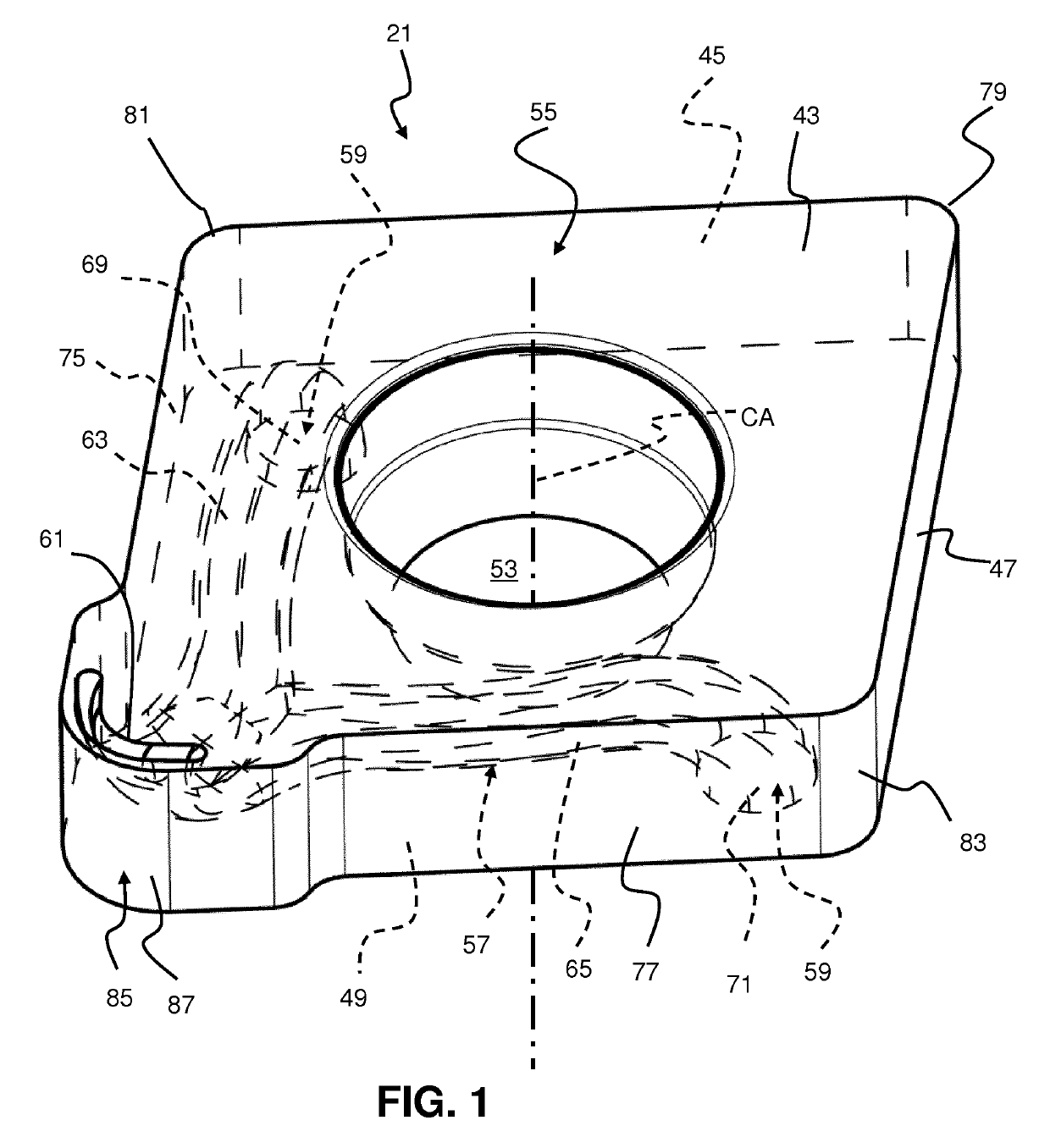
Figure 1 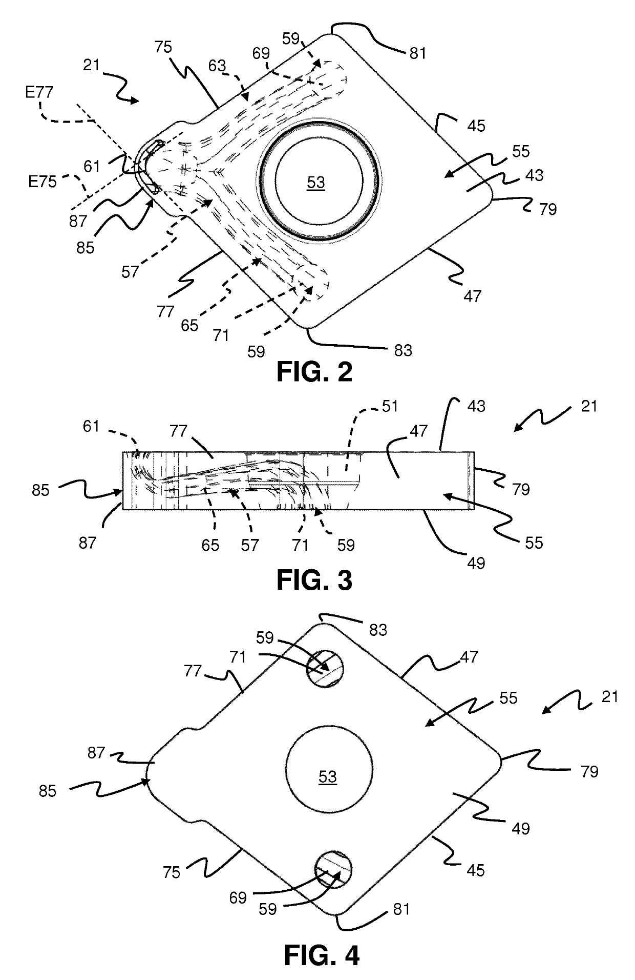
Figure 2 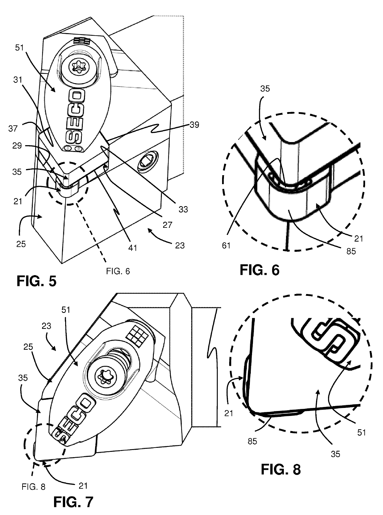
Figure 3
Abstract
Description
BACKGROUND AND SUMMARY
[0001] The present invention relates generally to anvils for cutting tools and, more particularly, to such anvils having fluid passages therein.
[0002] Cutting tools for modern metal cutting and other machining operations typically include toolholders with replaceable cutting inserts. The cutting inserts are typically made of much harder materials, such as sintered, cemented carbide, than the toolholders. The cutting inserts are typically clamped in recesses provided in the toolholders for the cutting inserts. Often, an anvil (sometimes referred to as a shim) is provided in the recess between the bottom surface of the recess and the bottom surface of the cutting insert. One purpose for providing an anvil is to position the cutting edge(s) of the cutting insert relative to the toolholder in a desired fashion.
[0003] Because of high temperatures generated during cutting operations, it is often desirable to provide cooling and / or lubricating fluid near the cutting edge...
Examples
Embodiment Construction
[0024]EP2946857A1, however, only provides a fluid passage through the anvil that is in a straight line. A passage having a straight line structure limits options available for providing fluid by the cutting edge. For example, in the event that the anvil is secured to the toolholder by a bolt or other structure extending through a hole in the anvil, the hole may make it impossible to provide a passage that extends along a straight line. Forming a passage that goes around the hole may require several manufacturing steps such as advanced drilling and / or blind plugging operations, adding to the cost of the cutting insert.
[0025]FIGS. 1-4 in the present patent application show an anvil 21 for a cutting tool 23 of the type shown in FIGS. 5-8. The cutting tool 23 illustrated in FIGS. 5-8 is a turning tool, however, the invention is not limited to turning tools and may be applicable to other tools that use anvils (also referred to as shims), such as rotating tools, such as milling tools. As ...