

Instant-on projector
a projector and instant technology, applied in the field of image projection systems, can solve the problems of difficult to achieve suitable projected image brightness, difficult to warm up hid arc lamps, and often less than satisfactory optical performance of conventional projectors
Patent Information
- Authority / Receiving Office
- US · United States
- Current Assignee / Owner
- Publication Date
- 2006-01-24
- Estimated Expiration
- Not applicable · inactive patent
Smart Images
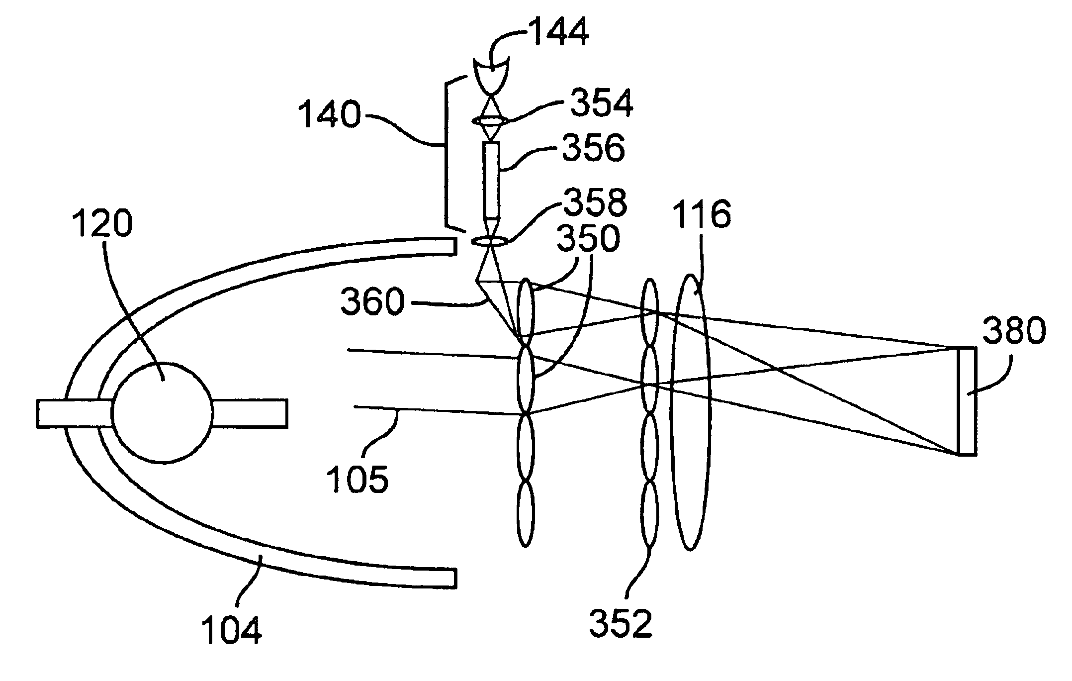
Figure 1 
Figure 2 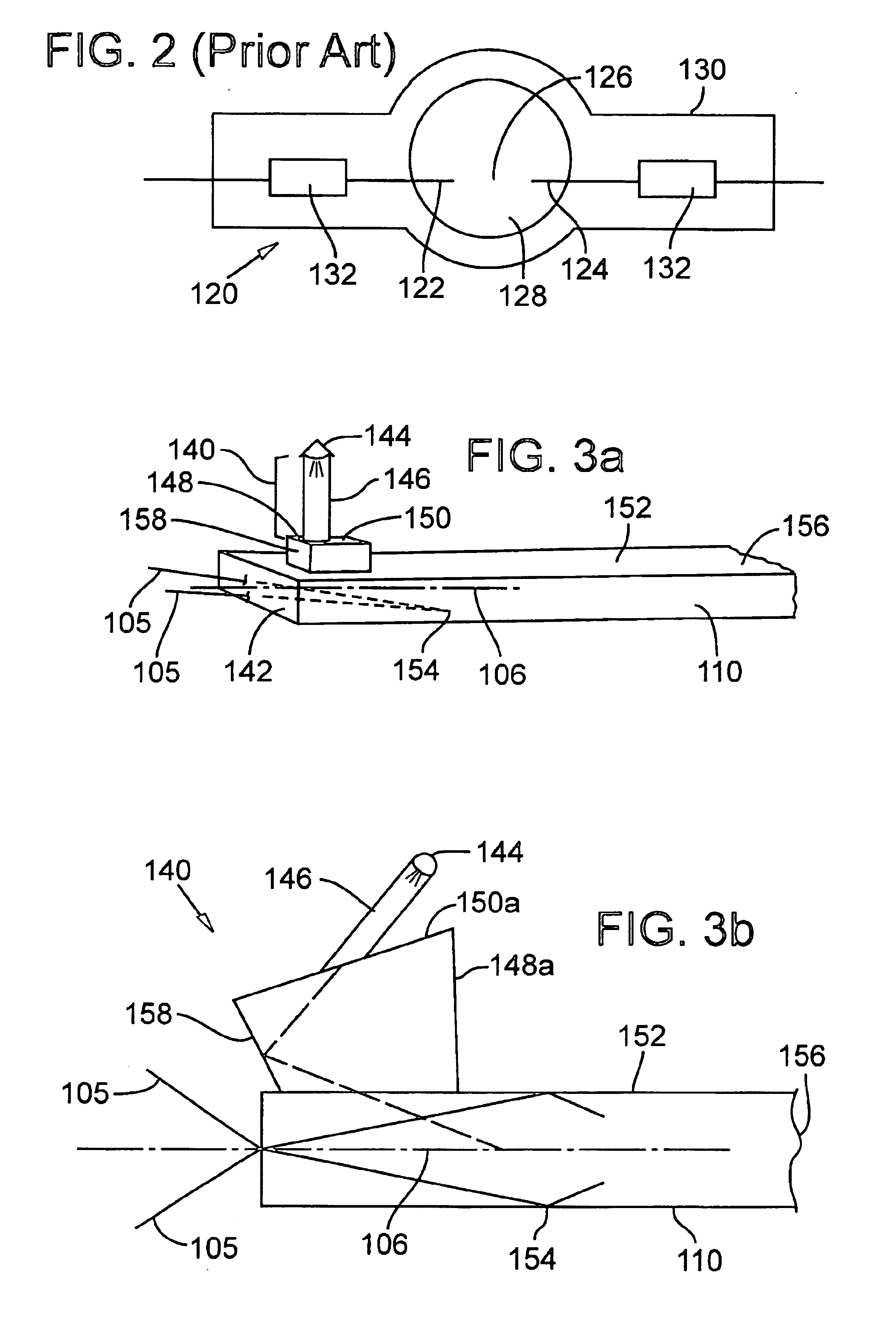
Figure 3
Abstract
Description
RELATED APPLICATION
[0001] The present application is a continuation-in-part application of U.S. Pat. No. 6,688,747, application Ser. No. 09 / 877,955, filed on Jun. 8, 2001 and issued on Feb. 10, 2004, entitled “Achieving Color Balance in Image Projection Systems by Injecting Compensating Light”.TECHNICAL FIELD
[0002] This invention relates to image projection systems and more particularly to a method for providing a user with an instant-on experience, and for improving the brightness and color balance of images produced by such projection systems.BACKGROUND OF THE INVENTION
[0003] Image projection systems have been used for many years to project motion pictures and still photographs onto screens for viewing. More recently, presentations using multimedia projection systems have become popular for conducting sales demonstrations, business meetings, and classroom instruction.
[0004] Color image projection systems may operate on the principle that color images are produced from the three primar...
Examples
first embodiment
[0033]FIG. 3a shows a schematic view of the present invention, in which an auxiliary light source 140 is affixed at a location near an entrance end 142 of an optical integrating device, preferably light tunnel 110. Auxiliary light source 140 preferably includes one or more solid state light-emitting devices 144, such as a light-emitting diode (LED), from which compensating light propagates through an optical fiber 146 into an optical coupling device, preferably a prism 148. Prism 148 directs the compensating light into light tunnel 110 at an appropriate angle to cause the compensating light to coincide with light rays 105 of polychromatic light propagating along primary light path 106.
[0034]In the embodiment depicted in FIG. 3a, optical fiber 146 is affixed to prism 148 on an input prism face 150 that is substantially parallel to a first light tunnel surface 152 to which prism 148 is affixed. Prism 148 is affixed at a location near entrance end 142 of light tunnel 110 upstream of a ...
second embodiment
[0060]In a second embodiment, the auxiliary light source is coupled to a light reflector adjacent to the primary light source and thereby allows the compensating light to propagate through the image projection system with the same efficiency as that of the light generated by the primary light source.
[0061]FIG. 14 shows a schematic diagram of a second embodiment of the present invention in which auxiliary light source 140 is positioned adjacent to an outer surface 186 of light reflector 104 and is coupled to primary light source 102, which is preferably an HID arc lamp 120. Auxiliary light source 140 emits a compensating light beam that is focused by an optical focusing element 180, and propagates through a compensating light entrance zone 184 on light reflector 104 to pass through arc gap 126 of arc lamp 120 and strike an inner surface 188 of light reflector 104.
[0062]To enable propagation of the compensating light beam through light reflector 104, inner surface 188 of light reflect...