

Seek error retry method of a disk device and disk device
a disk device and error retry technology, applied in the direction of recording information storage, maintaining head carrier alignment, instruments, etc., can solve the problems of easy clogging of the ramp mechanism, difficult use of the css (contact start-stop) method, and the head may easily climb onto the ramp mechanism. , to achieve the effect of reducing the retry time, preventing ramp wear and similar effects, and improving device reliability
Patent Information
- Authority / Receiving Office
- US · United States
- Patent Type
- Patents(United States)
- Current Assignee / Owner
- Publication Date
- 2006-09-26
Smart Images
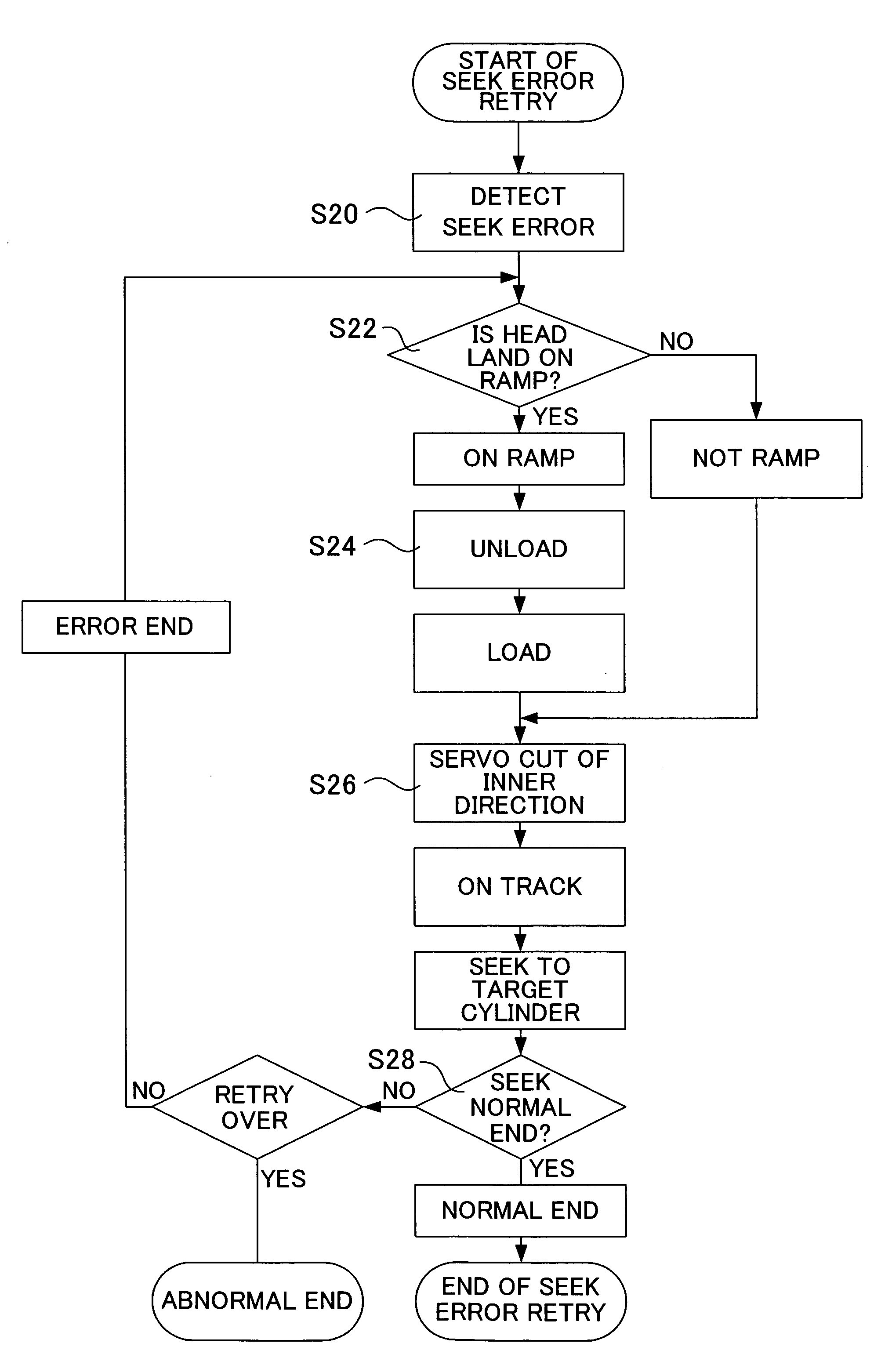
Figure 1 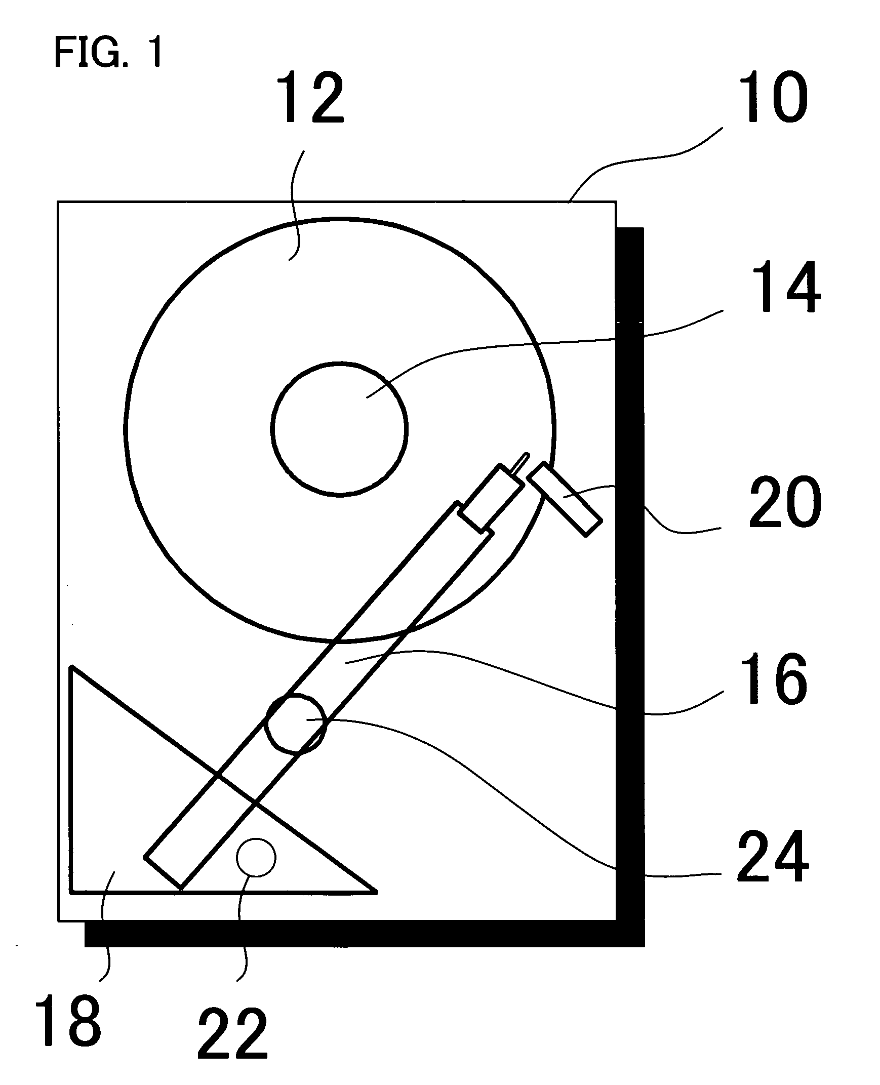
Figure 2 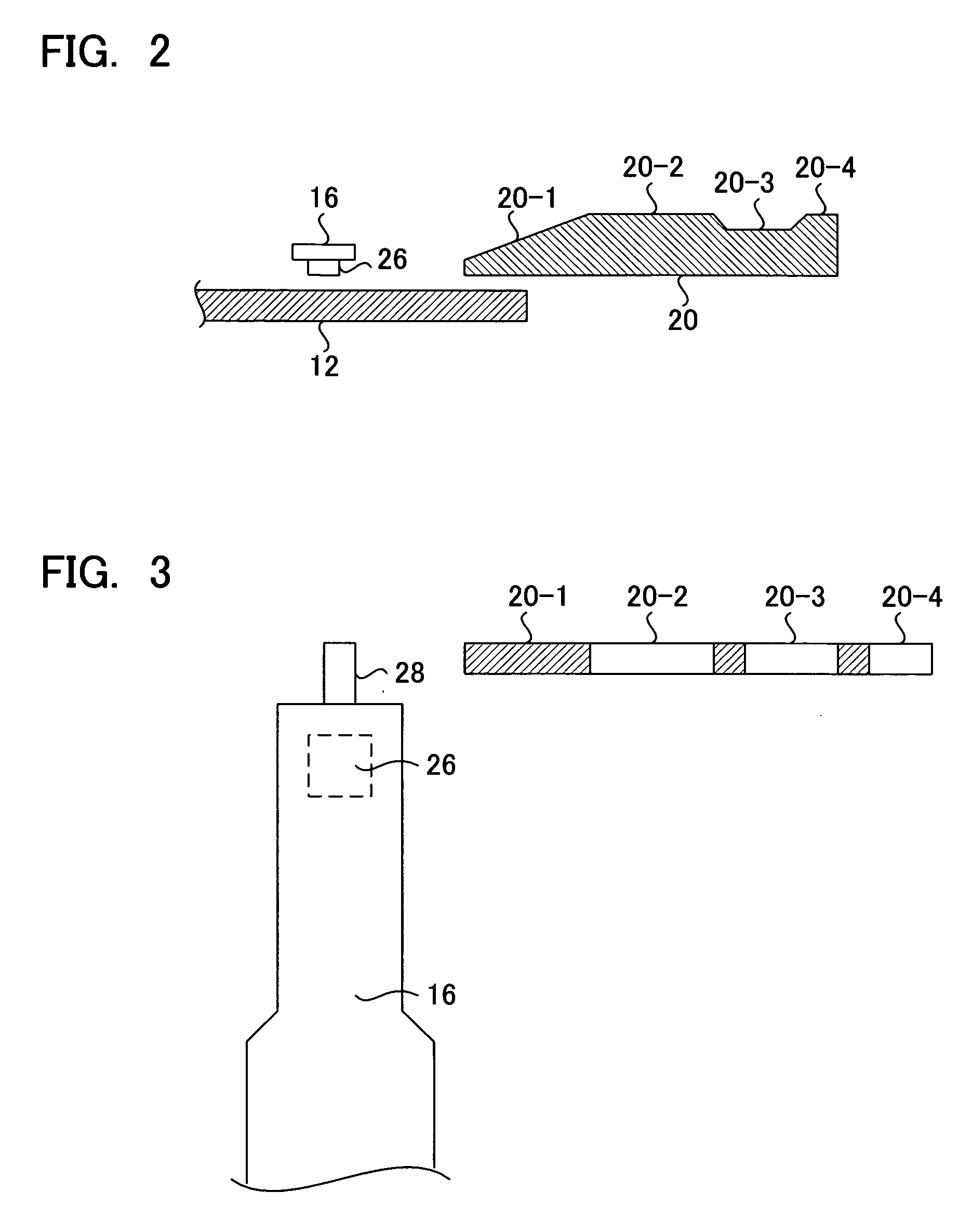
Figure 3
Abstract
Description
CROSS-REFERENCE TO RELATED APPLICATIONS
[0001] This application is based upon and claims the benefit of priority from the prior Japanese Patent Application No. 2005-023548, filed on Jan. 31, 2005, the entire contents of which are incorporated herein by reference.BACKGROUND OF THE INVENTION
[0002] 1. Field of the Invention
[0003] This invention relates to a seek error retry method of disk device and its disk device to perform retry control when a seek error has occurred during head seeking, and in particular relates to a seek error retry method of disk device and its disk device, which is suitable for a disk device having a ramp mechanism to retract a head from the disk media.
[0004] 2. Description of the Related Art
[0005] A disk device employing a magnetic disk, magneto-optical disk, optical disk, or other storage media performs a seek operation to position the head at a desired track on the disk. In such a disk device, as the head flying height is reduced, use of the CSS (Contact Start-Stop...
Examples
Embodiment Construction
[0037]Below, embodiments of the invention are explained, in the order of a disk device, seek error retry processing, and other embodiments.
Disk Device
[0038]FIG. 1 shows the configuration of the magnetic disk device of a first embodiment of the invention, FIG. 2 is a cross-sectional view of the ramp mechanism of FIG. 1, FIG. 3 is a top view of the ramp mechanism of FIG. 1, and FIG. 4 is a block diagram of the control unit in the magnetic disk device of FIG. 1. As the disk device, the example of a magnetic disk device is shown.
[0039]As shown in FIG. 1, the magnetic disk drive 10 has a magnetic disk 12; a spindle motor 14 which rotates the magnetic disk 12; an arm 16 having at the tip a head slider comprising a magnetic head 26; a VCM (Voice Coil Motor) 18 which moves the arm 16, comprising the head slider, in the radial direction of the magnetic disk 12; and a ramp 20, provided on the outer perimeter of the magnetic disk 12, to which the arm 16 is retracted.
[0040]The VCM 18 comprises ...