

Anti-reverse flow mechanism for centrifugal blowers
a centrifugal blower and reverse flow technology, which is applied in the direction of wind motors with parallel air flow, wind motors with perpendicular air flow, liquid fuel engine components, etc., can solve the problems of additional operational strain on the remaining operating blower, reducing the effectiveness of the cooling of the internal components of the machine,
Patent Information
- Authority / Receiving Office
- US · United States
- Patent Type
- Patents(United States)
- Current Assignee / Owner
- Publication Date
- 2006-10-31
- Estimated Expiration
- Not applicable · inactive patent
Smart Images
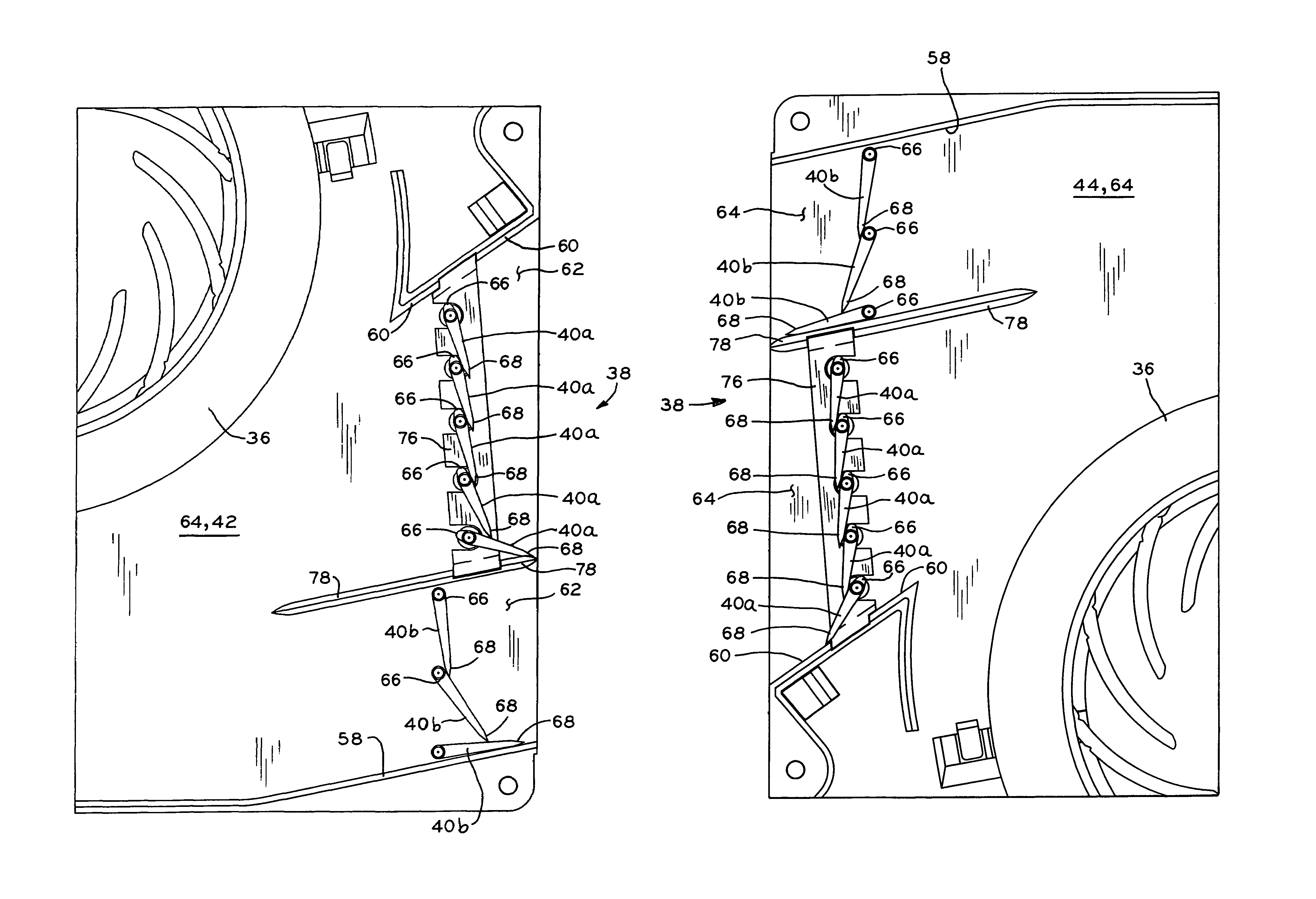
Figure 1 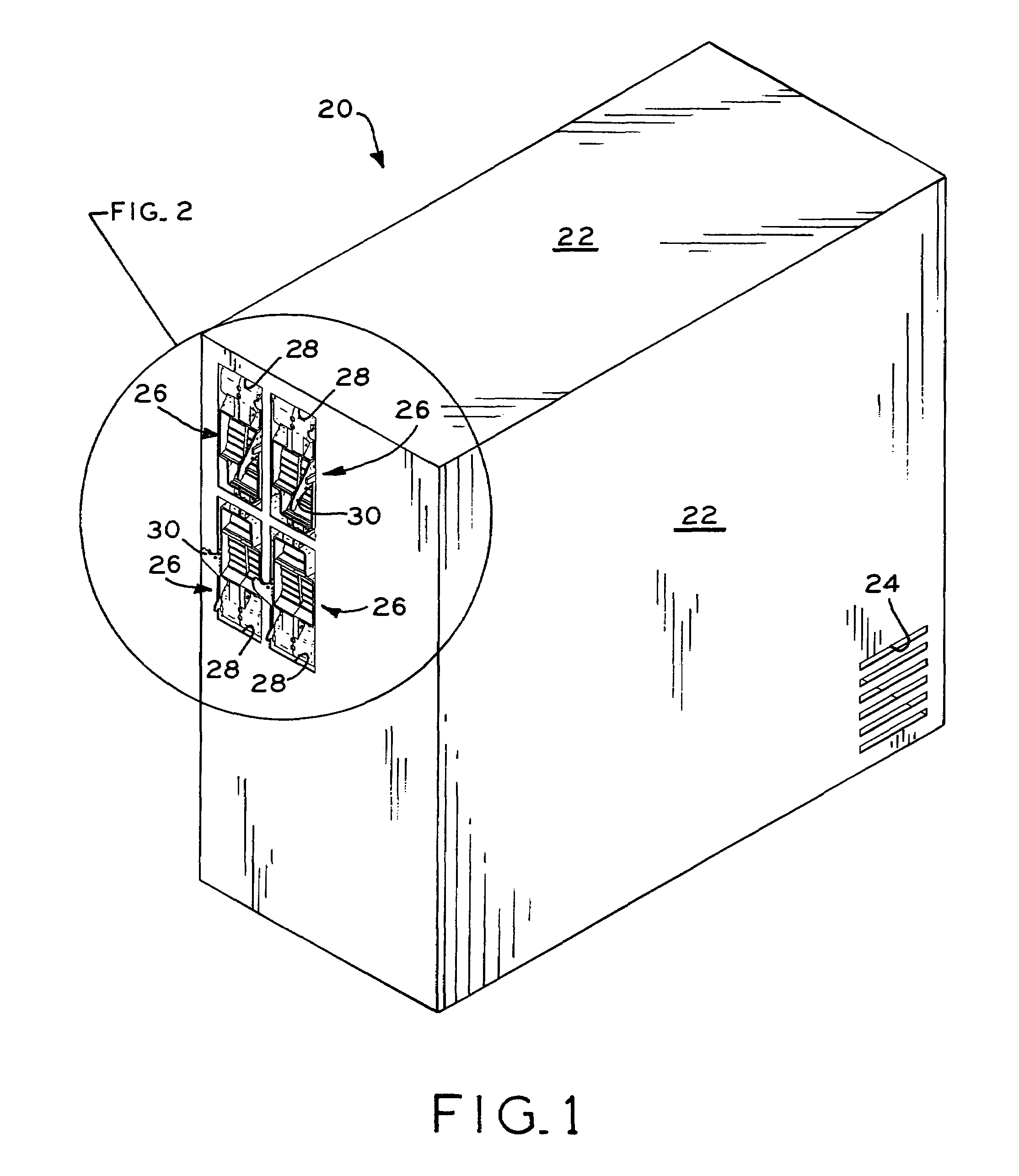
Figure 2 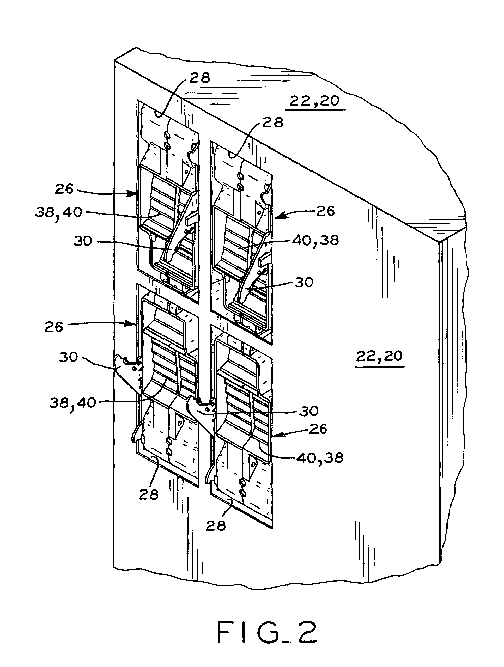
Figure 3
Abstract
Description
BACKGROUND OF THE INVENTION
[0001] 1. Field of the Invention
[0002] The present invention relates to blowers for circulating cooling air through machines, and in particular, the present invention relates to blowers which include an anti-reverse flow mechanism.
[0003] 2. Description of the Related Art
[0004] Many electrically-powered machines include a housing in which electrical components such as circuits and motors are contained. During running of the machines, the electrical components within the machines generate heat which must be continuously vented from the machines to cool the internal electrical components. Typically, such machines include one or more internal blowers, each including an electric motor connected to an impeller which is disposed within a blower housing, the blower housing having an inlet in airflow communication with the interior of the machine housing and an outlet in airflow communication with an opening in the machine housing. In operation, rotation of the impelle...
Examples
Embodiment Construction
[0033]Referring to FIG. 1, electrical machine 20 is shown, which may be a computer server, for example, or any other machine which includes a housing having internal electrical components such as circuit boards and electric motors, for example, which generate heat during operation and must therefore be cooled by a flow of cooling air through the machine while the machine is operating. Machine 20 generally includes a box-shaped housing 22 having a cooling air inlet 24, which is shown in FIG. 1 in the form of a plurality of slots in housing 22. A plurality of blowers 26, four of which are shown in FIGS. 1 and 2, are mounted within corresponding blower cavities 28 in housing 22 of machine 20. Latches 30 are pivotally mounted to blowers 26, and releasably engage cooperating latching structure (not shown) disposed within blower cavities 28 to secure and lock blowers 26 within blower cavities 28 of machine 20. Although blowers 26 are sized and adapted to be inserted within blower cavities...