
Series/parallel turbochargers and switchable high/low pressure EGR for internal combustion engines
a turbocharger and internal combustion engine technology, applied in the direction of machines/engines, mechanical equipment, electric control, etc., can solve the problems of additional warm-up time, turbo delay or lag, less desirable transient response, and small turbos with limited air handling capacity for higher engine speeds. , to achieve the effect of generating more boost, reducing inertia, and sufficient air handling capacity
Patent Information
- Authority / Receiving Office
- US · United States
- Patent Type
- Patents(United States)
- Current Assignee / Owner
- Publication Date
- 2007-01-23
- Estimated Expiration
- Not applicable · inactive patent
Smart Images
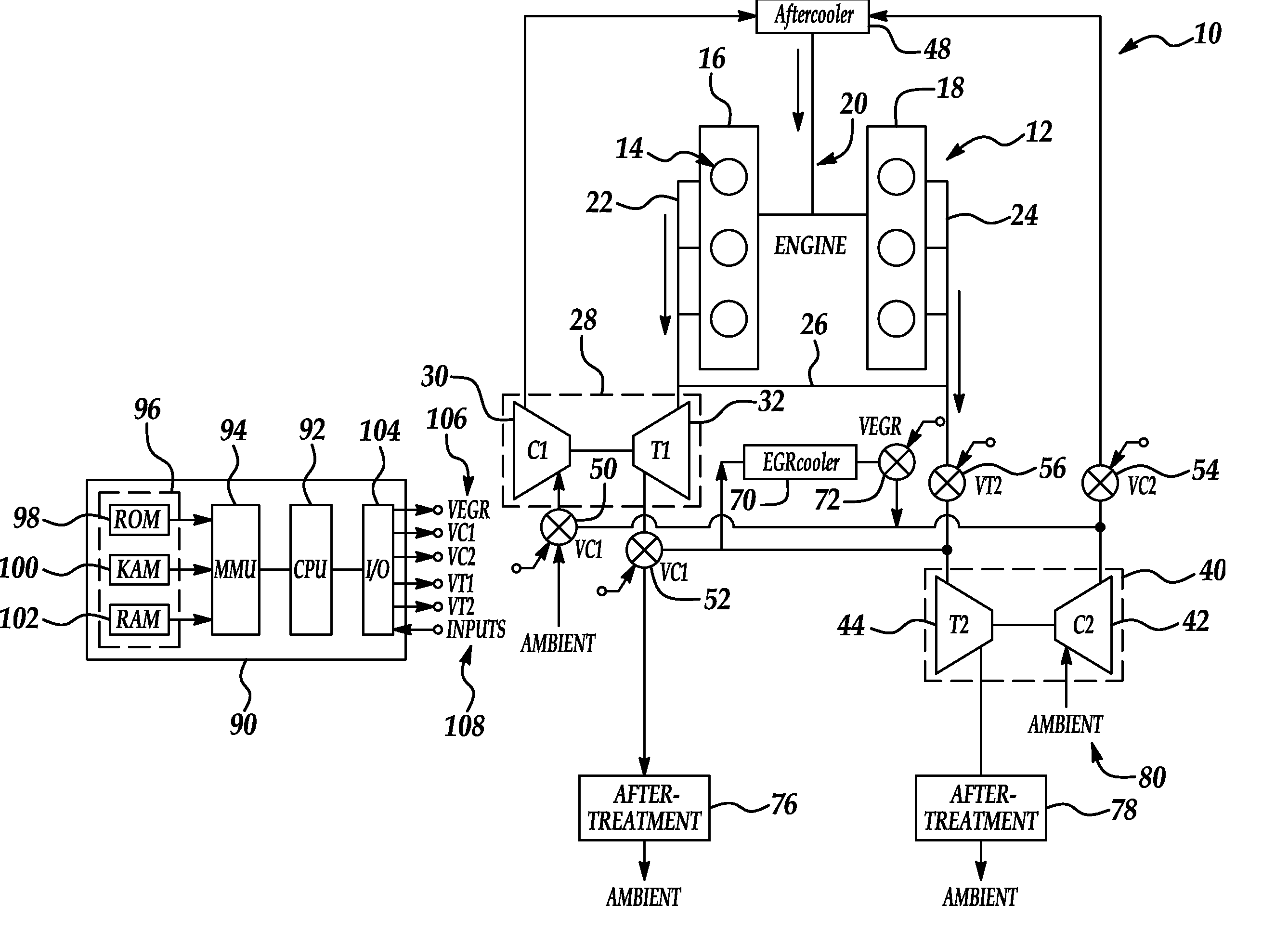
Figure 1 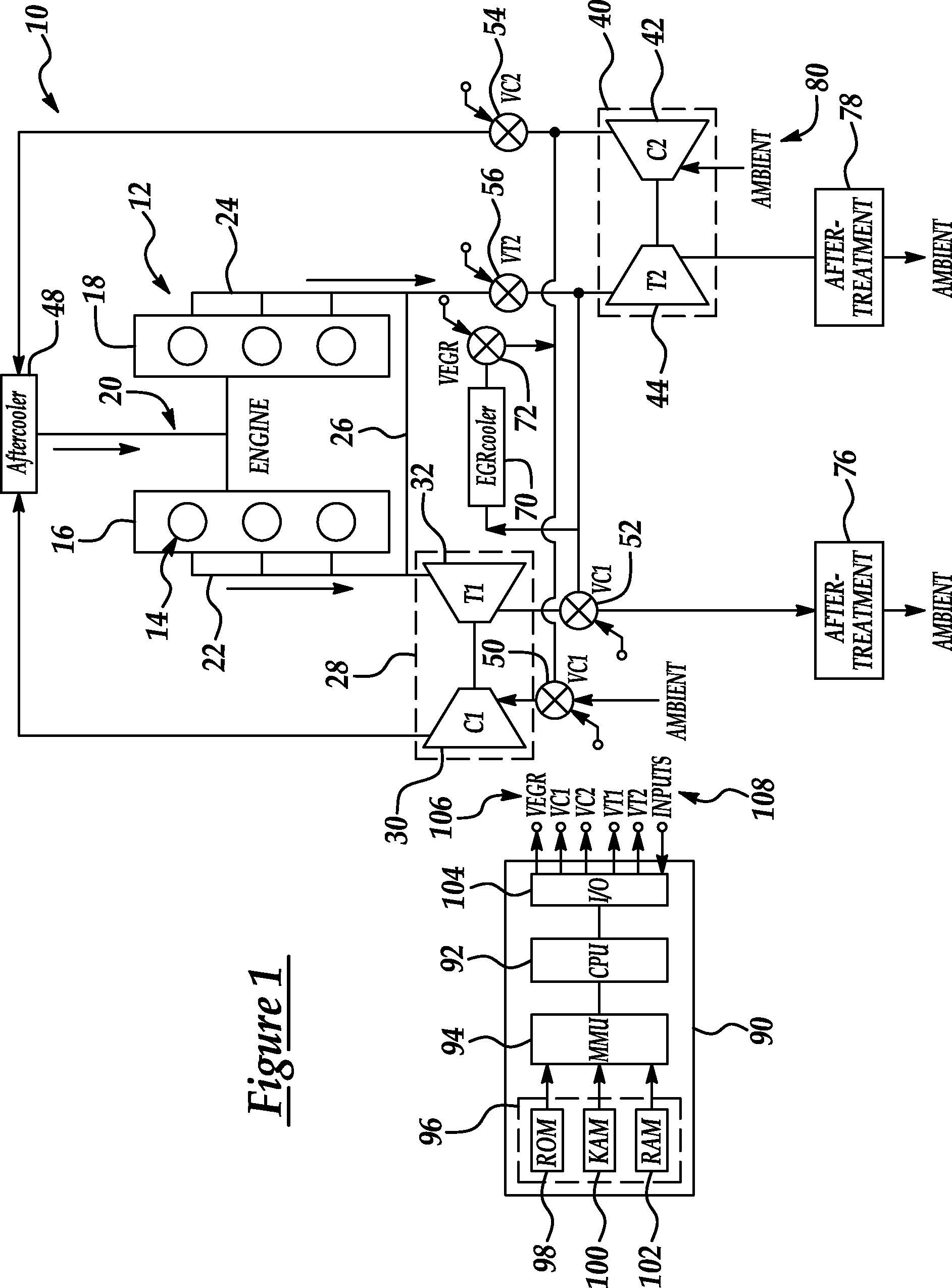
Figure 2 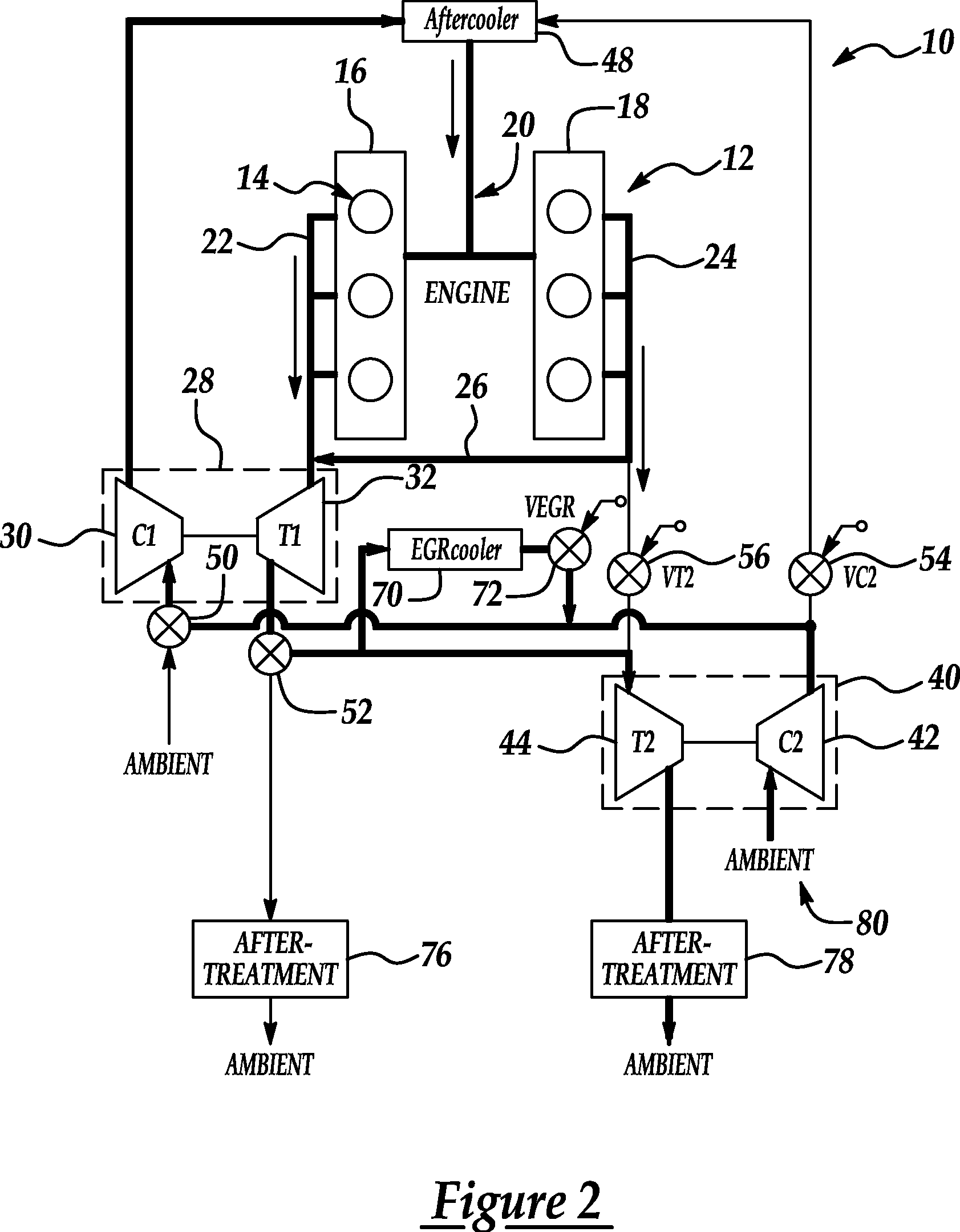
Figure 3
Abstract
Description
BACKGROUND OF INVENTION
[0001] 1. Field of the Invention
[0002] The present invention relates to systems and methods for turbocharging and providing exhaust gas recirculation for internal combustion engines.
[0003] 2. Background Art
[0004] Sizing a turbocharger for a particular engine application traditionally requires compromises to achieve a fast transient response from idle with a desired boost when launching a vehicle, especially when using exhaust gas recirculation (EGR), while providing sufficient air handling capacity at high engine speeds. Generally, a fast transient response requires a smaller turbo with lower inertia. However, a smaller turbo has limited air handling capacity for higher engine speeds. A turbo with sufficient airflow capacity for higher engine speeds generally has larger mass and inertia leading to noticeable turbo delay or lag and a less desirable transient response.
[0005] EGR handling and control strategies typically require similar compromises. At light load and ...
Examples
Embodiment Construction
[0023]A block diagram illustrating a system or method for turbocharged an internal combustion engine according to one embodiment of the present invention is shown in FIG. 1. As illustrated in FIG. 1, system 10 includes an internal combustion engine 12 having a plurality of cylinders 14. In the example illustrated in FIG. 1, cylinders 14 are arranged in two banks 16 and 18. However, the present invention is independent of the particular cylinder arrangement and may also be applied to in-line configurations, for example. Similarly, while a six-cylinder engine is illustrated, the present invention may be applied to internal combustion engines having any number of cylinders. Preferably, the present invention is applied to turbocharged internal combustion engines utilizing compression ignition technology, such as diesel engines. However, those of ordinary skill in the art will recognize that the present invention is generally independent of the particular type of engine.
[0024]Intake mani...