
Mailbox system
Patent Information
- Authority / Receiving Office
- US · United States
- Current Assignee / Owner
- Publication Date
- 2008-06-03
- Estimated Expiration
- Not applicable · inactive patent
Smart Images
Figure 1 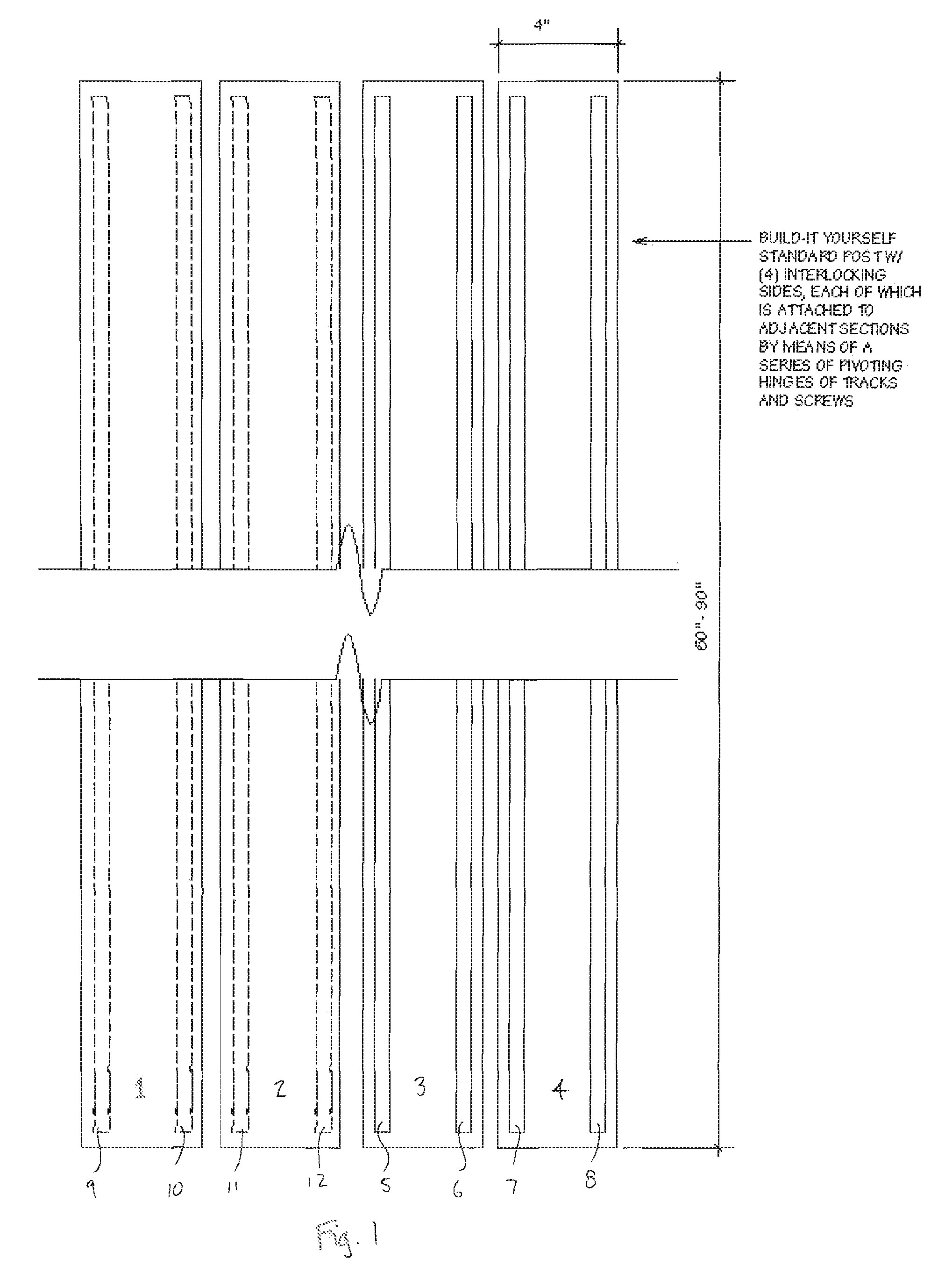
Figure 2 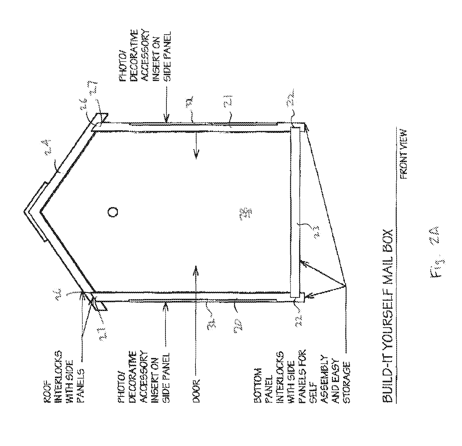
Figure 3
Abstract
Description
BACKGROUND OF THE INVENTION
[0001] 1. Field of the Invention
[0002] The present invention relates to design and construction of curbside contemporary mailboxes.
[0003] 2. Applicable Regulations and Prior Art
[0004] The US Postal Service has issued 39 CFR Part 111 expressly incorporated herein by reference, which, among other things, governs curbside mailboxes. See also, Domestic Mail Manual DO41, (DMM Issue 58 Updated Jan. 6, 2005), and USPS-STD-7B (Feb. 8, 2001, Fed. Register 66(27) 9509-9522), expressly incorporated herein by reference in their entirety.
[0005] Contemporary mailboxes provide increased manufacturing flexibility over traditional domed designs, but as a whole the differences have been most aesthetic. A particular issue in traditional and most contemporary mailbox designs is that they are distributed in a state ready for use, and thus have a large void volume as delivered. This makes shipping inefficient and forces retailers to allocate a large amount of shelf and warehouse spa...
Examples
Embodiment Construction
[0045]FIG. 1 shows a modular post construction, wherein a hollow post is formed of four shell sections 1, 2, 3, 4, preferably formed of metal. The four sections are, for example, extruded aluminum, held together, for example, by a interlocking sections 5, 6, 7, 8, 9, 10, 11, 12. Alternately, a hinge structure (with optional screws) or trapezoidal tongue in a corresponding groove structure may be provided to connect the faces into a hollow structure. A cap at the top, and an optional stake at the bottom (not shown in FIG. 1), may be used to maintain alignment along the axis of the post.
[0046]FIGS. 2A and 2B show, respectively, a front and side view, respectively, of an embodiment of the invention with a “V” shaped sloping roof. FIGS. 2C and 2D show, respectively, a front and side view, respectively, of an embodiment of the invention with a “U” shaped curved roof. Each of the sides 20, 21 is provided with a slot 22 for insertion of the base 23. Likewise, the roof 24 (“V” shaped in FIG...