

High temperature steam valve and steam turbine plant
a high-temperature steam valve and steam turbine technology, which is applied in steam engine plants, machines/engines, mechanical equipment, etc., can solve the problems of high-temperature steam existence, valve rod creep deformation, and severe for the constituent materials of steam valves
Patent Information
- Authority / Receiving Office
- US · United States
- Patent Type
- Patents(United States)
- Current Assignee / Owner
- Publication Date
- 2009-01-27
Smart Images
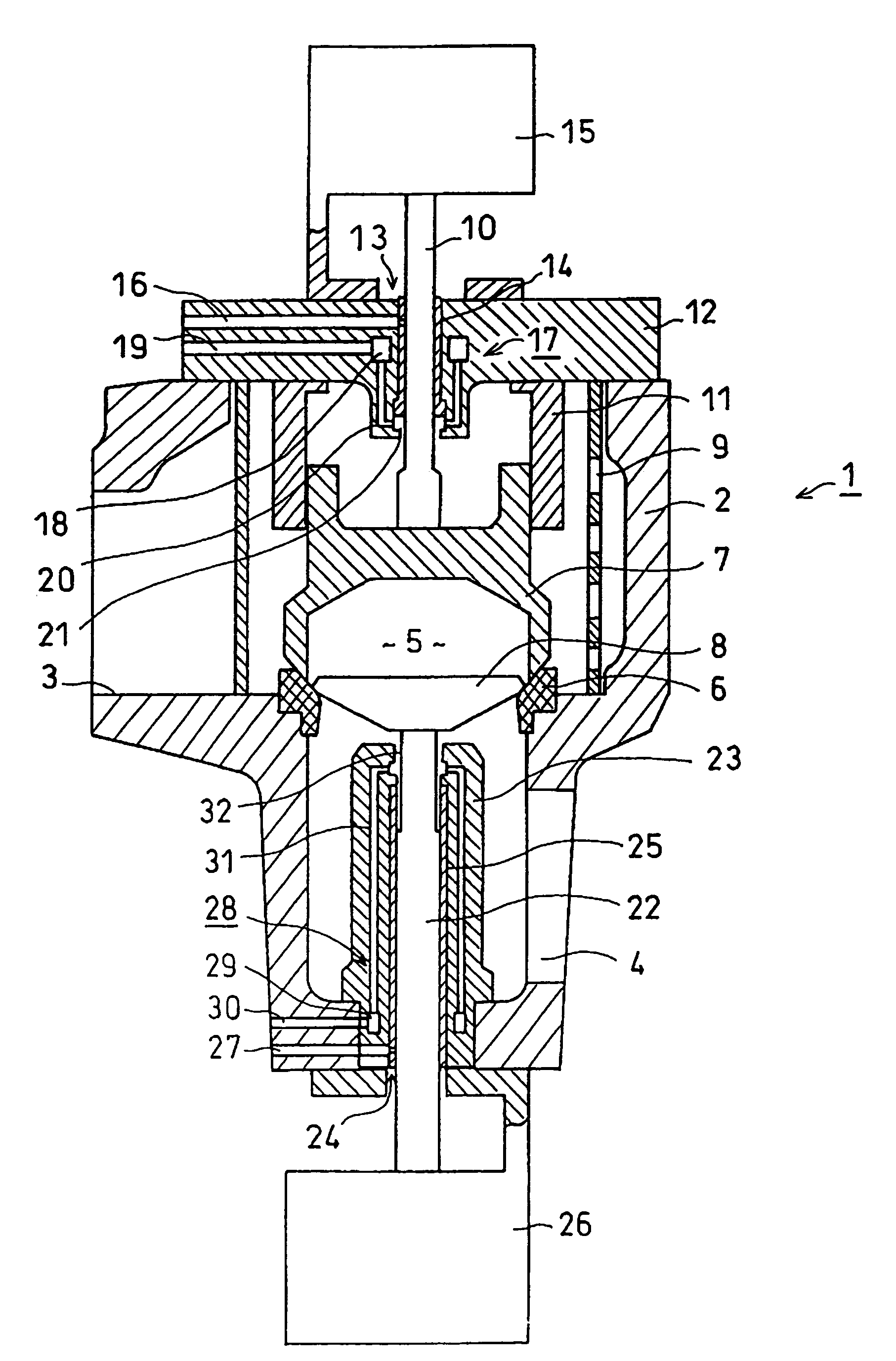
Figure 1 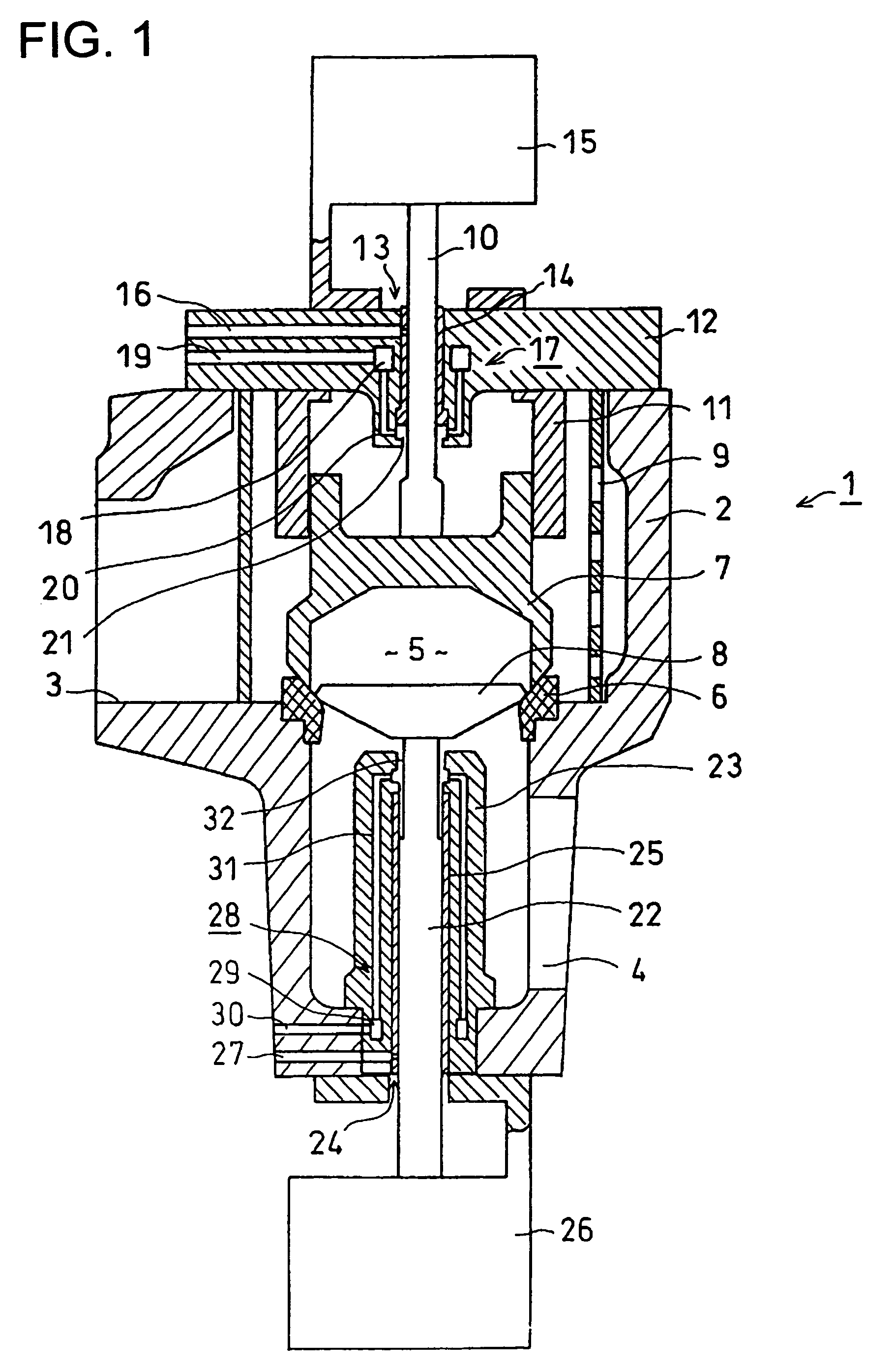
Figure 2 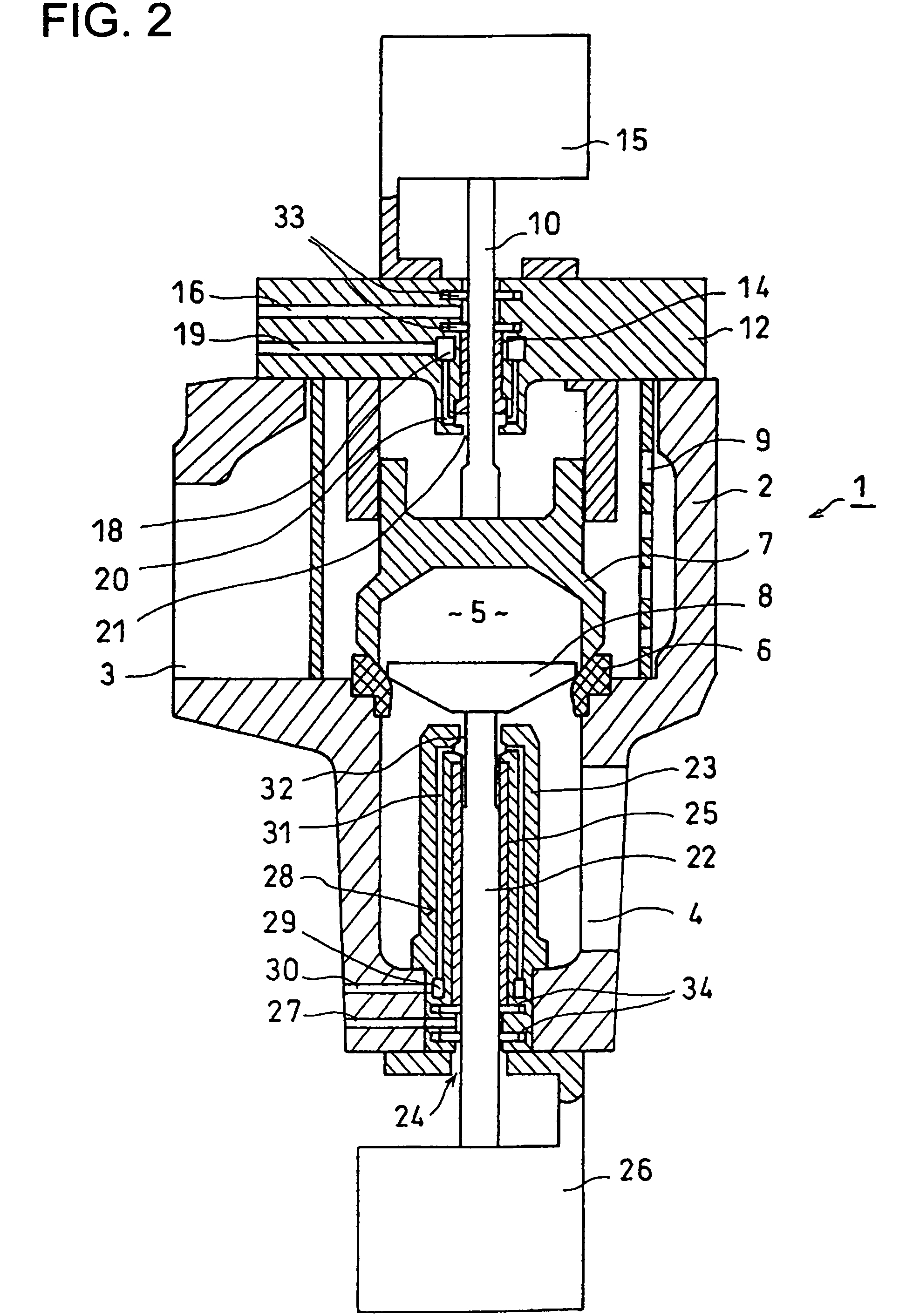
Figure 3
Abstract
Description
CROSS-REFERENCE TO RELATED APPLICATIONS
[0001] This application is based upon and claims the benefit of priority from the prior Japanese Patent Application No. 2004-260587, filed on Sep. 8, 2004; the entire content of which is incorporated herein by reference.BACKGROUND OF THE INVENTION
[0002] The present invention is generally related to a high temperature steam valve, and more particularly to a high temperature steam valve employing a cooling mechanism to cool valve constituent elements. The present invention is also related to a steam turbine plant having a high temperature steam valve.
[0003] Recently, it is required that steam turbines of thermal electric power plants be more effective in the light of the environmental problems, so that the steam temperature tends to be raised higher. The steam condition now adopted widely is of about 169 kg / cm2 and 566 degrees Celsius, or of about 246 kg / cm2 and 566 degrees Celsius as shown in Japanese Patent Application Publication Hei 7-247806, th...
Examples
first embodiment
[0021]FIG. 1 is a vertical cross sectional view of the embodiment in which the present invention is applied to the composite-type reheat high temperature steam valve.
[0022]In FIG. 1, the fundamental structure of the composite-type reheat high temperature steam valve will be explained first. Numeral “1” represents the entire composite-type reheat high temperature steam valve. Numeral “2” represents the valve casing where a main steam inlet portion 3 on the left side as shown in the figure and a main steam outlet portion 4 on the opposite right bottom as shown in the figure are provided. A valve seat 6 is placed in a valve chest 5 formed between the main steam inlet portion 3 and the main steam outlet portion 4. A first valve element 7 and a second valve element 8 are driven to rise or descend toward the valve seat 6 from the bottom or the top of the figure. Numeral “9” represents a cylindrical strainer for eliminating dusts in the main steam.
[0023]The first valve element 7 has a near...
second embodiment
[0035]The second embodiment of the present invention is now explained referring to FIGS. 2, 4 and 5. This embodiment is also applied, like the first embodiment, to the composite-type reheat high temperature steam valve, so that each part corresponding to the FIG. 1 is denoted by the same numeral and explanation thereof will be appropriately omitted.
[0036]In FIG. 2, the main aspect of the second embodiment is that two piston rings 33 and two piston rings 34 are positioned. The openings of the steam vent holes 16 and 27 facing the peripheries of the valve rods 10 and 22, respectively, are positioned between the piston rings 33 and between the piston rings 34, respectively. The bushes 14, 25 are split into plural pieces. The other structures are the same as FIG. 1 mentioned above.
[0037]In the case of the second embodiment, the bush 14 does not fully penetrate the valve lid 12 but is mounted up to approximately the middle portion of the valve lid 12 in the thickness direction thereof fr...
third embodiment
[0042]Referring to FIGS. 3, 4 and 5, the third embodiment of the present invention is now explained. This embodiment shows an example applied to a main steam stop valve. In FIG. 3, the main steam stop valve 100 of the third embodiment has one valve element, so that the valve-rod penetrating portion 13 shown in FIG. 1 is not provided in the valve lid 12. Only the valve-rod penetrating portion 24 is provided at the bottom of the valve casing 2. The valve casing 2 of this embodiment is provided with the main steam inlet portion 3 on the left side of the figure and the main steam outlet portion 4 at the opposite bottom portion thereof on the right side of the figure. The valve seat 6 and the valve element 8 are located in the valve chest 5 formed between the main steam inlet portion 3 and the main steam outlet portion 4. The valve element is driven from the bottom side of the figure toward the valve seat 6 so that it can touch and detach the valve seat 6. Movement of the valve element 8...