
System and method for securing a rotor to a motor drive shaft using cam fasteners
Patent Information
- Authority / Receiving Office
- US · United States
- Current Assignee / Owner
- Publication Date
- 2009-02-03
Smart Images
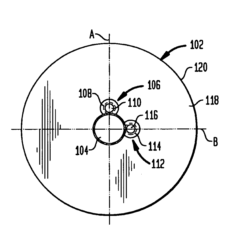
Figure 1 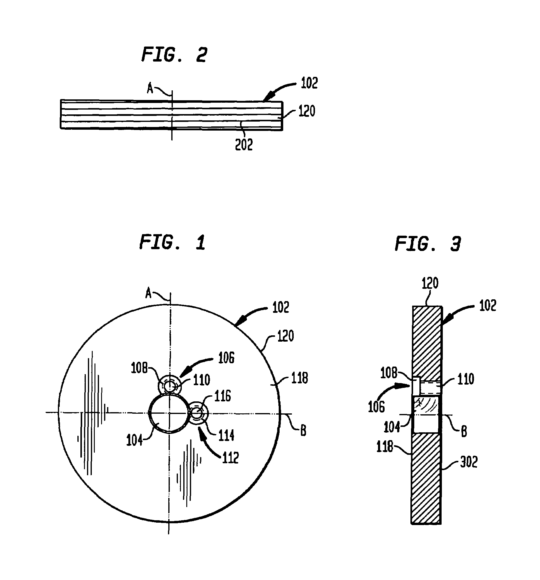
Figure 2 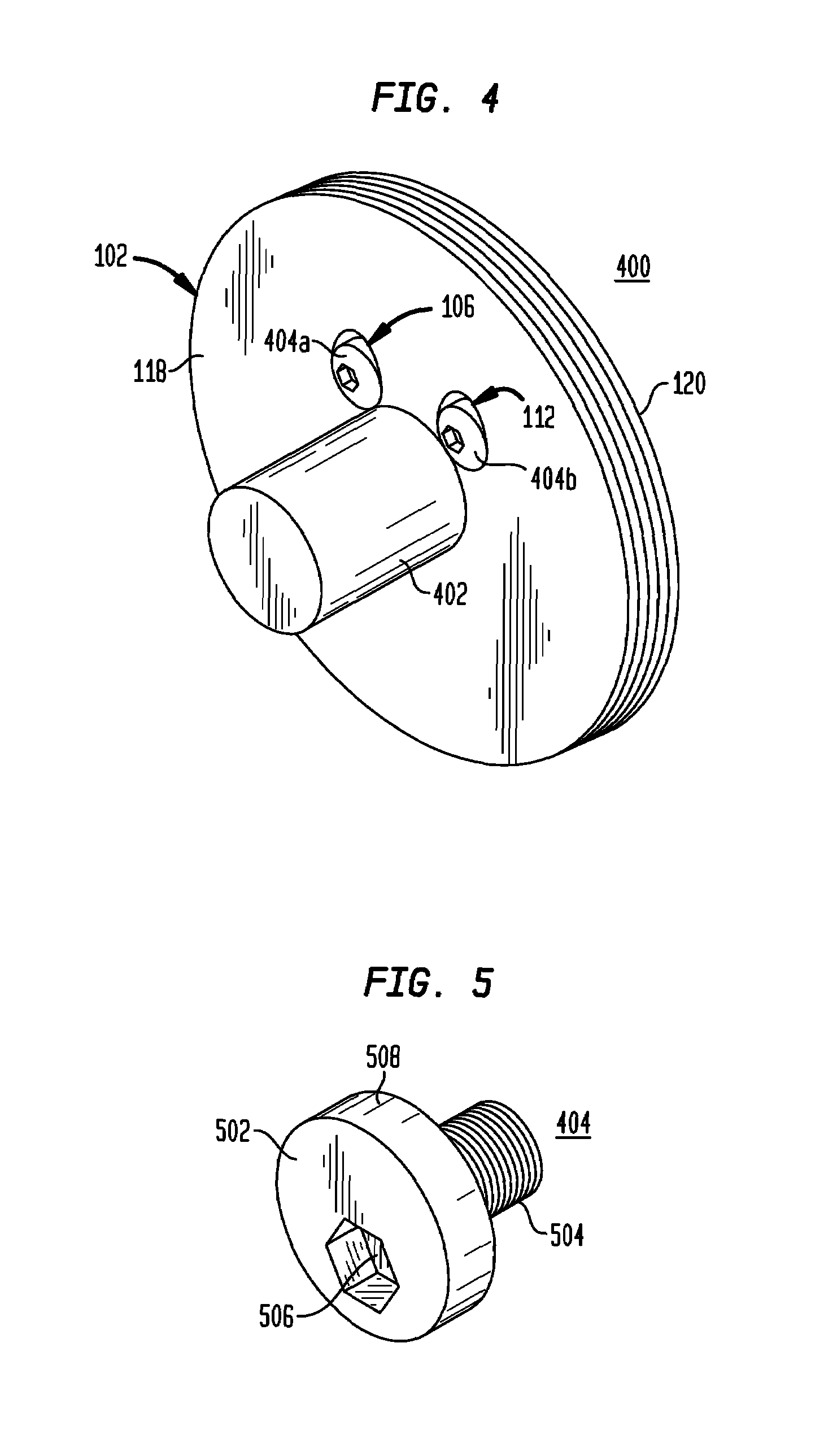
Figure 3
Abstract
Description
BACKGROUND OF THE INVENTION
[0001] 1. Technical Field
[0002] The present invention relates to rotors, and in particular, to a magnetic encoded rotor incorporating a means for securing the rotor to a motor drive shaft, the means incorporating one or more cam-type fasteners.
[0003] 2. Related Art
[0004] There are various systems and methods for mounting modular magnetic encoder rotors to a motor drive shaft (or motor shaft). However, there are disadvantages with each of these current systems.
[0005] A first system is directed to a rotor having an external hub encircling and extending away from the central aperture. The external hub typically has a diameter less than the outer diameter of the rotor and extends from the face of the hub a relatively short distance. A plurality of set screws is inserted through holes in the hub to engage the motor shaft. Upon tightening, the set screws secure the rotor to the motor shaft. In this embodiment, the external hub is typically positioned external to a st...
Examples
Embodiment Construction
[0019]The rotor assembly of the present invention is shown in the accompanying figures. FIGS. 1-3 show the preferred embodiment of a rotor 102 having a central bore 104 positioned about the intersection of a first, vertical, axis A and a second, horizontal, axis B wherein the first axis A is perpendicular to the second axis B. This central bore 104 has a diameter slightly larger than the diameter of the motor shaft. The rotor 102 has a first stepped bore 106 consisting of a tapped hole 110 through the thickness of the rotor 102 and a counterbored hole 108. The tapped hole 110 and counterbored hole 108 are to accommodate the cam screw described below. The first stepped bore 106 is positioned adjacent to and adjoining with the central bore 104 aligned with the axis A such that the counterbored hole 108 intersects with the central bore 104.
[0020]In the preferred embodiment, about one quarter of the circumference of the counterbored hole 108 intersects with the central bore 104. In addi...