
Non-reciprocal circuit device
a circuit device and non-reciprocal technology, applied in the direction of fixed capacitor details, electrical apparatus, fixed capacitor combinations, etc., can solve the problems of reducing production yield, many two-pair terminal isolators failing to have the desired electric characteristics, etc., and achieve excellent electric characteristics and reduce capacitance variations.
Patent Information
- Authority / Receiving Office
- US · United States
- Patent Type
- Patents(United States)
- Current Assignee / Owner
- Publication Date
- 2009-04-21
Smart Images
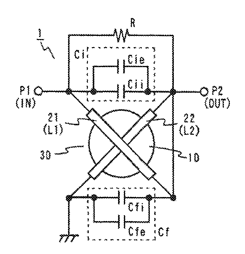
Figure 1 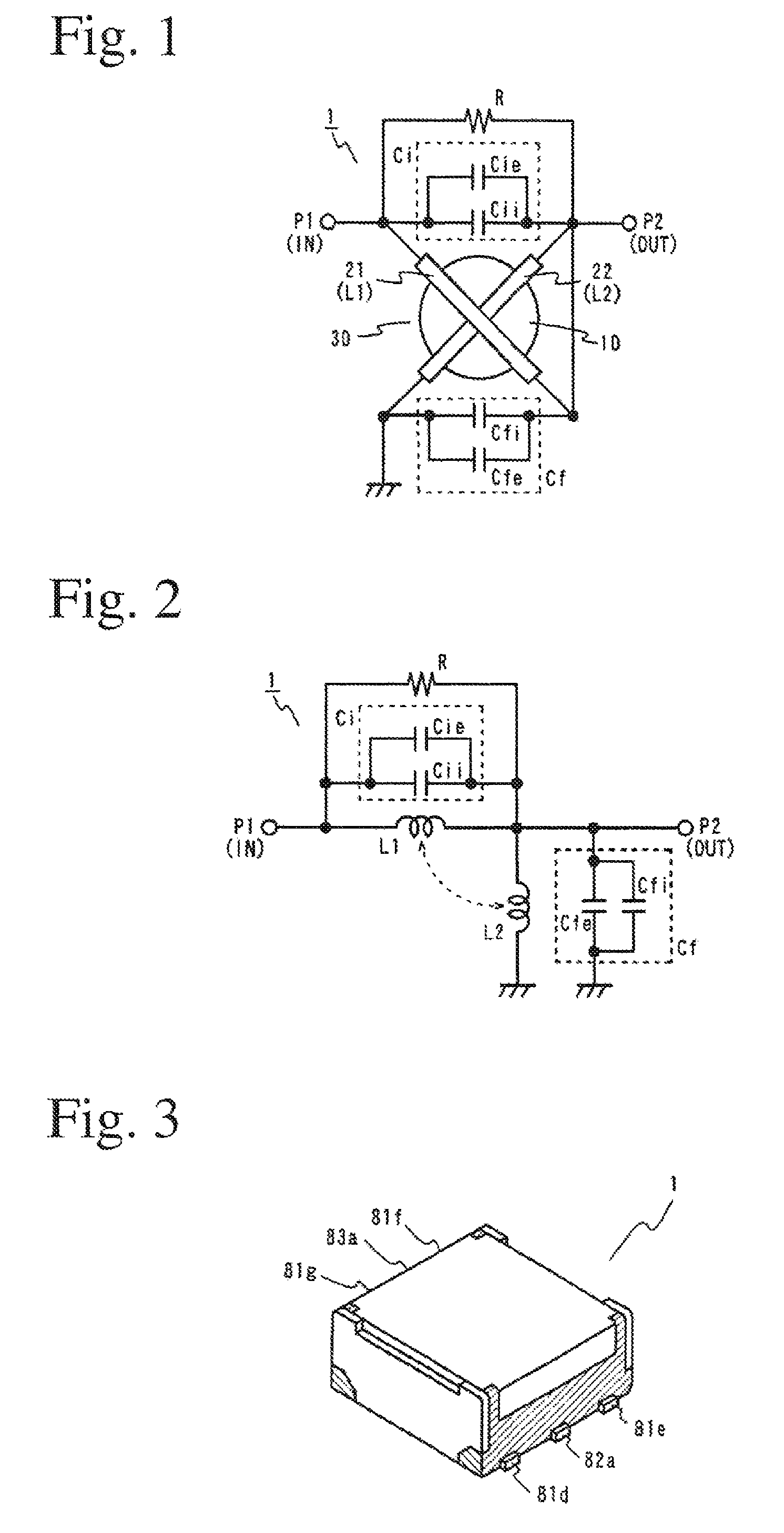
Figure 2 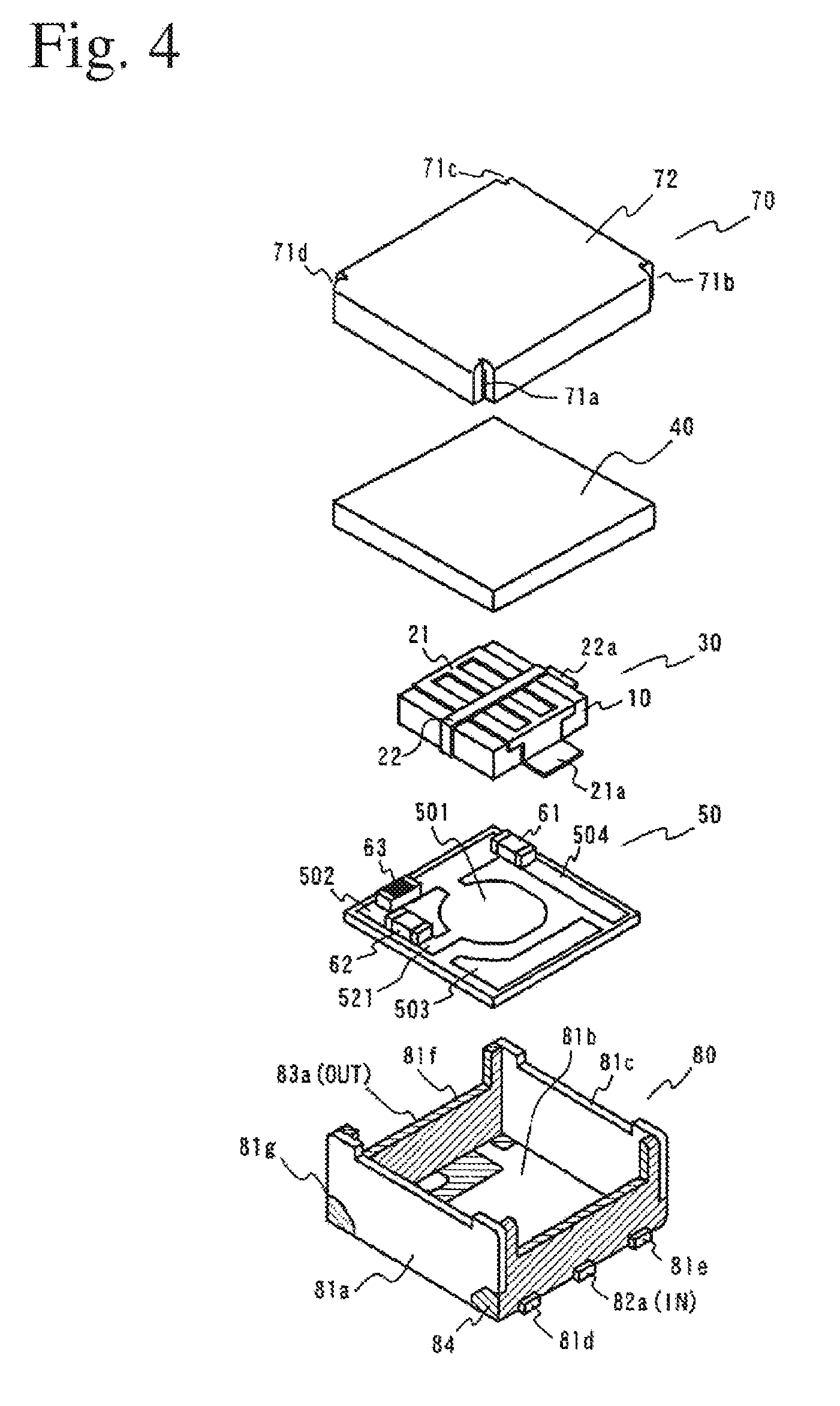
Figure 3
Abstract
Description
FIELD OF THE INVENTION
[0001] The present invention relates to a non-reciprocal circuit device having non-reciprocal transmission characteristics to high-frequency signals, particularly to a non-reciprocal circuit device generally called “isolator,” which is used in mobile communications systems such as cell phones, etc.BACKGROUND OF THE INVENTION
[0002] Non-reciprocal circuit devices such as isolators, etc. are widely used in mobile communications apparatuses utilizing frequency bands from several hundreds MHz to ten-odd GHz, such as base stations for personal handy phones PHS, cell phones, etc. The isolator is disposed, for instance, between a power amplifier and an antenna in a transmission path in a mobile communications apparatus, to prevent unnecessary signals from flowing back to the power amplifier and stabilize impedance on the load side of the power amplifier. Accordingly, the isolator is required to have excellent insertion loss characteristics, reflection loss characteristic...
Examples
example 1
[0071]With the capacitors Cii, Cfi formed in the multilayer substrates set to have capacitances of 27.6 pF and 17.1 pF, respectively, about 5% smaller than the set values of the first and second capacitance elements Ci, Cf. pluralities of motherboards each having 1500 (50×30) multilayer substrates were produced. The capacitance distribution of the capacitance elements Cfi in 1500 multilayer substrates arbitrarily selected from those obtained by dividing these motherboards is shown in FIG. 13. The capacitors Cfi had capacitances varying in a range of 16.6-17.8 pF like those of Conventional Example 1.
[0072]With respect to each of these multilayer substrates, the capacitance of each capacitor Cfi was measured, and when the measured value was 16.6 pF or more and less than 17.0 pF, a chip capacitor of 1.2 pF as a correcting chip capacitor Cfe was mounted onto the multilayer substrate. Similarly mounted were a chip capacitor of 1.0 pF when the measured value is 17.0 pF or more and less th...