
Cold runner injection mold having an insulated gate
a technology of injection molding and gate, which is applied in the field of injection molding and injection molding apparatus for molding a small and light optical element, can solve the problems of weak pressure applied to the resin in the cavity, short supply of resin to compensate for shrinkage of the resin, and low accuracy of fine configuration of a surface and a smooth surface, so as to improve the accuracy of transfer and fine configuration , the effect of accurate smooth surfa
Patent Information
- Authority / Receiving Office
- US · United States
- Patent Type
- Patents(United States)
- Current Assignee / Owner
- Publication Date
- 2010-05-04
- Estimated Expiration
- Not applicable · inactive patent
Smart Images
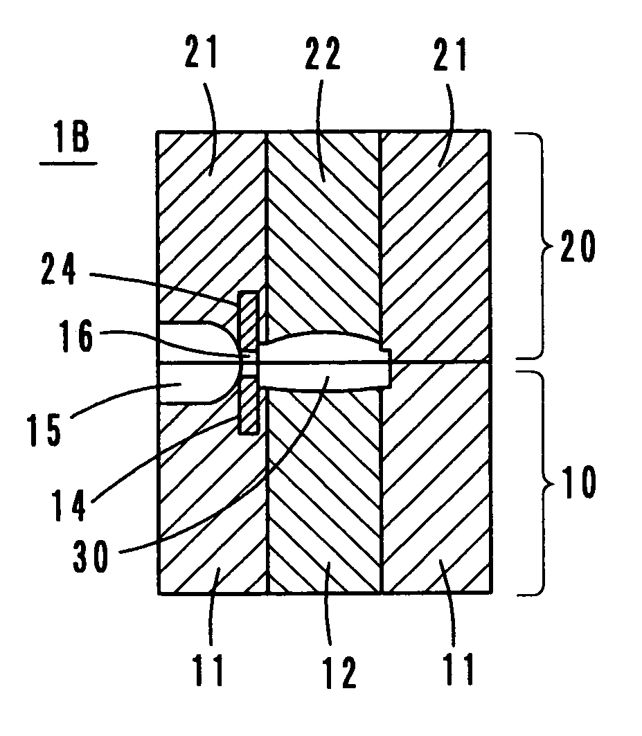
Figure 1 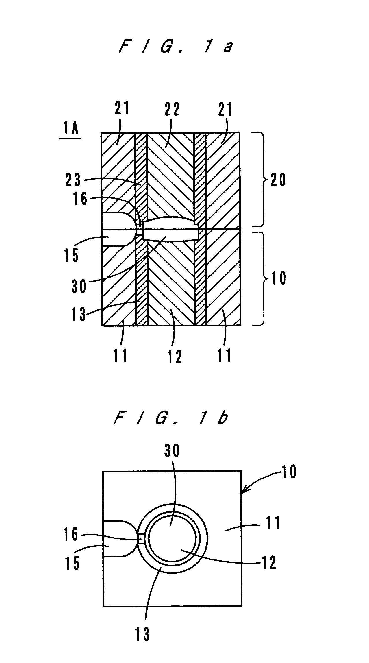
Figure 2 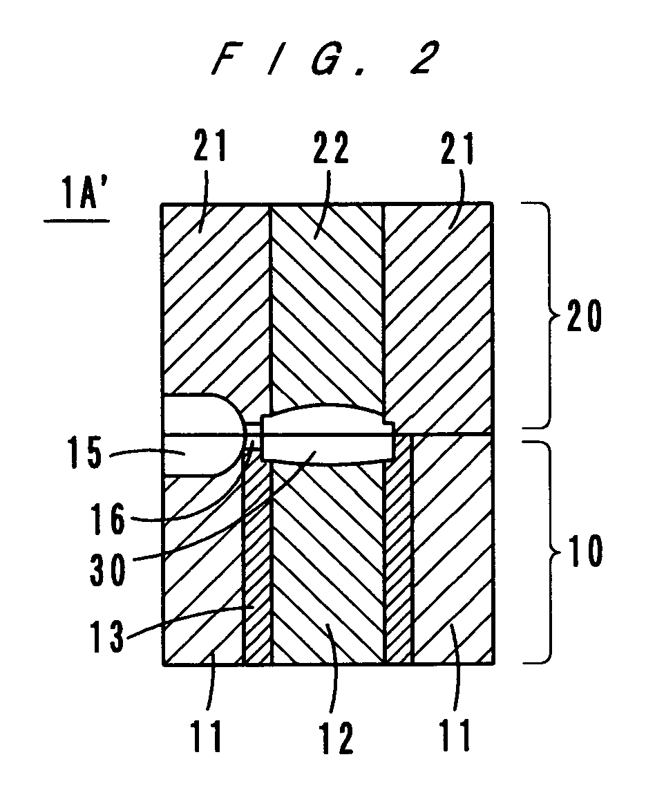
Figure 3
Abstract
Description
[0001] This application is based on Japanese application No. 2004-191835 filed on Jun. 29, 2004, the content of which is herein incorporated by reference.BACKGROUND OF THE INVENTION
[0002] 1. Field of the Invention
[0003] The present invention relates to an injection mold and an injection molding apparatus, and more particularly to an injection mold and an injection molding apparatus for molding a small and light optical element, such as a lens.
[0004] 2. Description of Related Art
[0005] In recent years, with improvement of resin materials and injection molding techniques, small and light resin lenses have been developed, and a demand for use of these resin lenses as optical elements in optical pick-up devices and portable telephones has been stronger. In order to produce such resin lenses, molds which permit accurate transfer of fine configurations for diffraction elements and smooth surfaces or the like are required.
[0006] Generally, a gate of a mold is narrow, and in a pressure retention ...
Examples
first embodiment
See FIGS. 1a, 1b and 2
[0021]As FIGS. 1a and 1b show, a mold 1A according to a first embodiment of the present invention comprises a movable mold 10 and a fixed mold 20. The movable mold 10 comprises bases 11 and 12, and a sleeve-like heat insulator 13. The fixed mold 20 comprises bases 21 and 22, and a sleeve-like heat insulator 23. A cavity 30 is formed of mutually opposite end faces of the bases (cores) 12 and 22, and sides of the heat insulators 13 and 23.
[0022]A runner 15 is formed in the parting surface between the bases 11 and 21. A gate 16 is formed in the heat insulators 13 and 23 to be located between the runner 15 and the cavity 30. More specifically, the gate 16 is formed of recesses made in the mutually opposite end surfaces of the heat insulators 13 and 23.
[0023]The surface of the cavity 30 is finished in accordance with the configuration of a product, such as a lens, and the cavity 30 may have a surface processed layer of nickel plating.
[0024]The bases 11, 12, 21 and 2...
second embodiment
See FIGS. 3a and 3b
[0028]FIGS. 3a and 3b show a mold 1B according to a second embodiment of the present invention. As FIGS. 3a and 3b show, heat insulator chips 14 and 24 are provided in the mold bases 11 and 21, respectively. A cavity 30 is formed of mutually opposite end surfaces of the mold bases (cores) 12 and 22.
[0029]A runner 15 is formed on the parting surface of the bases 11 and 21. A gate 16 is formed between the runner and the cavity 30 of recesses made in the mutually opposite end surfaces of the heat insulator chips 14 and 24.
[0030]The bases 11, 12, 21 and 22 can be made of the materials named in the description of the first embodiment. For the insulator chips 14 and 24, materials with relatively low coefficients of heat conductivity as described in the first embodiment, such as stainless steel, titanium alloy, nickel alloy, ceramic, etc., are usable.
[0031]Like the modification shown in FIG. 2, in the second embodiment also, it is possible to provide only the heat insul...
third embodiment
See FIGS. 4a and 4b
[0032]FIGS. 4a and 4b show a mold 1C according to a third embodiment of the present invention. In the mold 1C, a gate 16 is formed of recesses made in the mutually opposite end surfaces of the mold bases 11 and 21, and the inner surface of the gate 16 is coated with a heat insulator. The heat insulator coating may be a ceramic flame coating, a metal plating such as nickel, cobalt, etc., a titanium evaporation coating such as titanium nitride or a heat resistance polymer coating such as polyimide resin (with a coefficient of heat conductivity of 0.28 W / mK). For the bases 11, 12, 21 and 22, the materials named in the description of the first embodiment are usable.
[0033]Like the modification shown in FIG. 2, in the third embodiment also, it is possible to provide the heat insulating coating only for the movable mold 10. The effect of the present invention, which will be described later, is obtained by providing the heat insulating coating. The effect can be obtained...