
Friction plate for wet-type multiplate clutch
a multi-plate clutch and friction plate technology, which is applied in the direction of friction clutches, yielding couplings, clutches, etc., can solve the problems of insufficient lube oil drainage and inability to satisfactorily meet the demand for a further reduction in drag torque, so as to reduce drag torque and reduce drag torque
Patent Information
- Authority / Receiving Office
- US · United States
- Patent Type
- Patents(United States)
- Current Assignee / Owner
- Publication Date
- 2011-07-19
- Estimated Expiration
- Not applicable · inactive patent
Smart Images

Figure 1 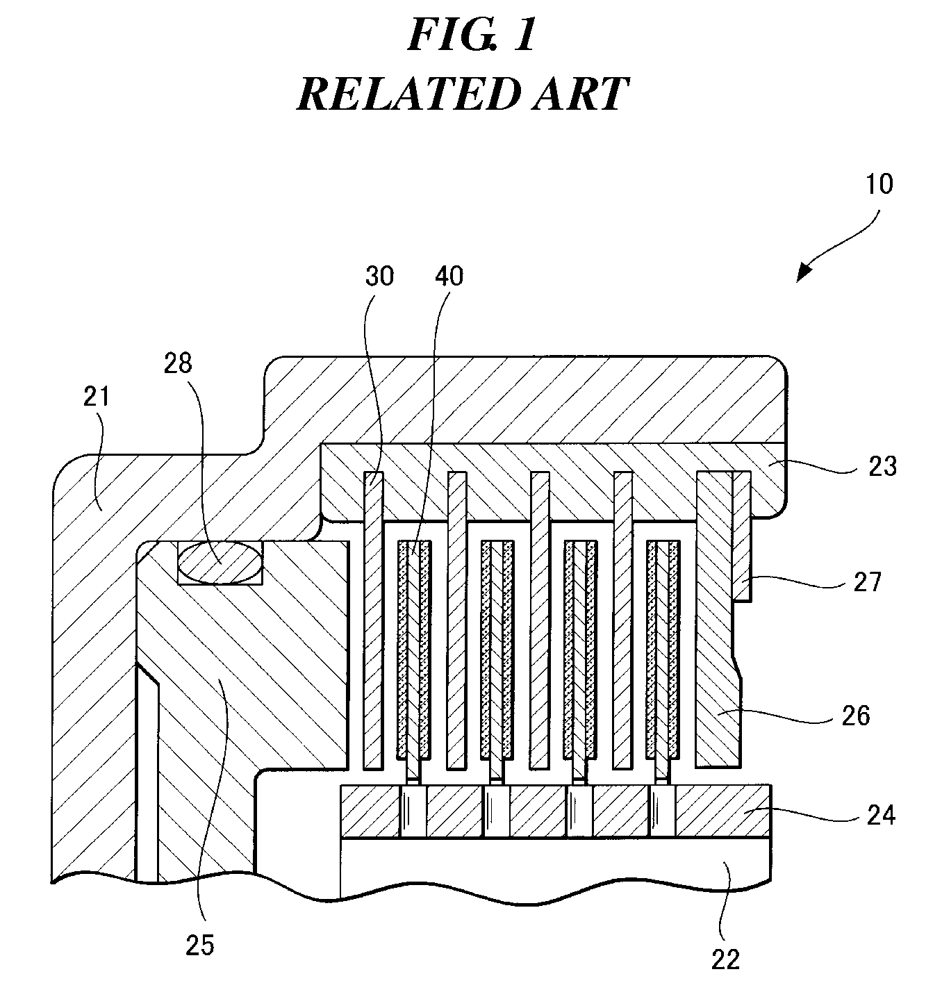
Figure 2 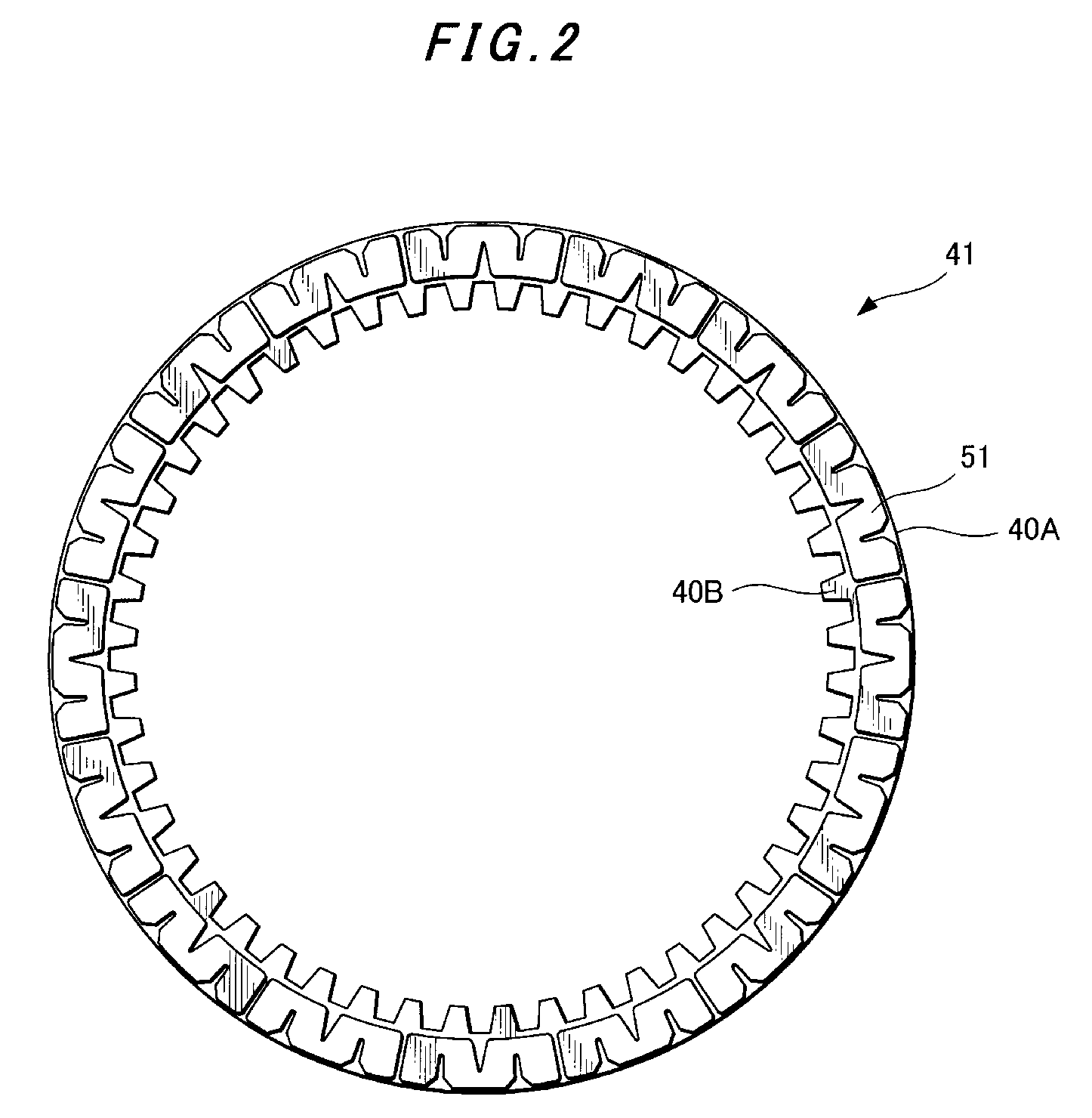
Figure 3
Abstract
Description
CROSS-REFERENCE TO RELATED APPLICATION
[0001] This application claims the priority of Japanese Patent Application 2007-066664 filed Mar. 15, 2007, which is incorporated herein by reference.BACKGROUND
[0002] 1. Field
[0003] The presently disclosed subject matter relates to a friction plate for a wet-type multiplate clutch useful as a clutch, brake or the like in an automatic transmission.
[0004] 2. Description of the Related Art
[0005] FIG. 1 is a cross-sectional view illustrating the fundamental construction of a wet-type multiplate clutch 10. FIG. 1 shows a clutch casing 21, a counterpart hub 22 to which a rotary torque is transmitted, a spline groove 23 formed on the clutch casing 21, a spline groove 24 formed on the hub 22, a piston 25 for pressing separator plates 30 and friction plates 40 against a backing plate 26, a snap ring 27 supporting the backing plate 26, and a sealing ring 28 for the piston 25. The separator plates 30 are maintained in fitting engagement with the spline groove 2...
Examples
first embodiment
[0020]FIG. 2 is a front view of a friction plate 41 according to the presently disclosed subject matter, and FIG. 3 is an enlarged fragmentary view of the friction plate 41 of FIG. 2. FIGS. 2 and 3 show a core plate 40A, segment pieces 51 of a friction lining, spline teeth 40B to be brought into fitting engagement with a counterpart hub, first oil grooves 61 and their end portions 61A, and second oil grooves 71 and their end portions 71A.
[0021]As illustrated in FIG. 3, each second oil groove 71 is provided with an opening 71B flared outwardly in a radial direction. As the rotational speed of a clutch becomes higher, a negative pressure is produced between plates. Under this negative pressure, air is drawn onto friction surfaces to reduce a drag torque. The outwardly flared configuration of the opening 71B of each second oil groove 71 facilitates the draw of air from the radially-outer side of the plates, so that more air is drawn onto the friction surfaces to reduce a drag torque.
[0...
second embodiment
[0023]FIG. 4 is a front view similar to FIG. 2, but illustrates a friction plate 42 according to the FIG. 5 is an enlarged fragmentary view of the friction plate 42 of FIG. 4. FIGS. 4 and 5 depict a core plate 40A, segment pieces 52 of a friction lining, spline teeth 40B to be brought into fitting engagement with a counterpart hub, first oil grooves 62, and second oil grooves 72 and their end portions 72A.
[0024]As illustrated in FIG. 5, each second oil groove 72 is provided with an opening 72B flared outwardly in a radial direction. As the rotational speed of a clutch becomes higher, a negative pressure is produced between plates. Under this negative pressure, air is drawn onto friction surfaces to reduce a drag torque. The outwardly flared configuration of the opening 72B of each second oil groove 72 facilitates the draw of air from the radially-outer side of the plates, so that more air is drawn onto the friction surfaces to reduce a drag torque.
[0025]Quick drainage of lube oil f...