
LED retrofit for fluorescent backlit signs
a backlit sign and led technology, applied in lighting and heating apparatus, instruments, lighting support devices, etc., can solve the problems of more components, more complex assembly, and lower efficiency, and achieve the effect of more components, lower efficiency, and more expensive components
Patent Information
- Authority / Receiving Office
- US · United States
- Patent Type
- Patents(United States)
- Current Assignee / Owner
- Publication Date
- 2011-12-27
- Estimated Expiration
- Not applicable · inactive patent
Smart Images
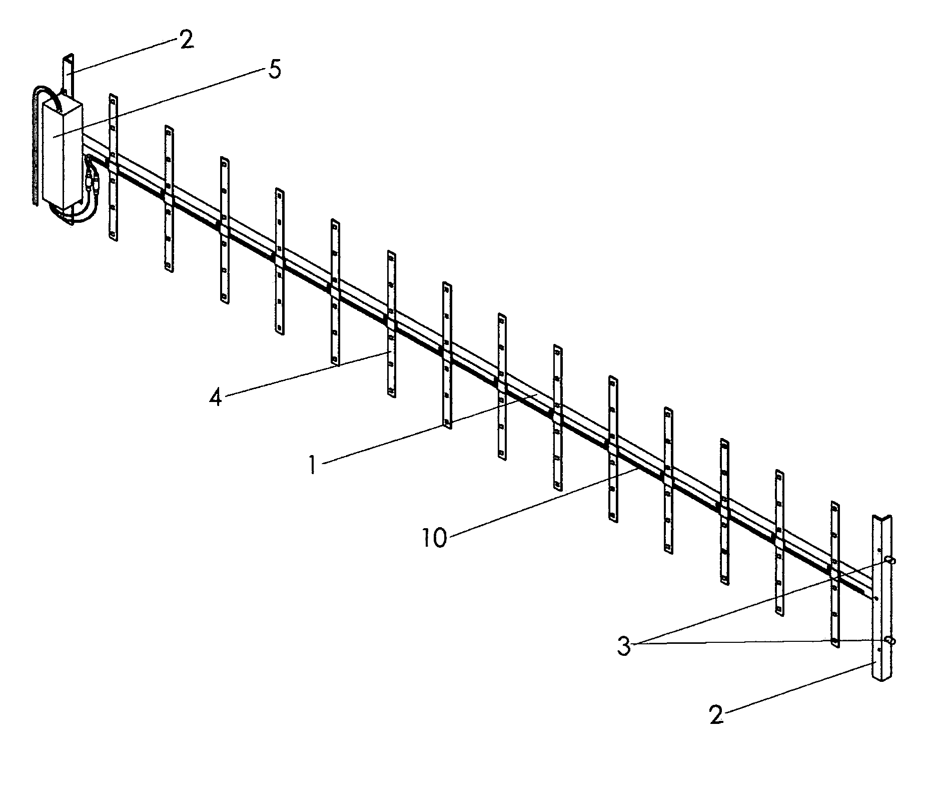
Figure 1 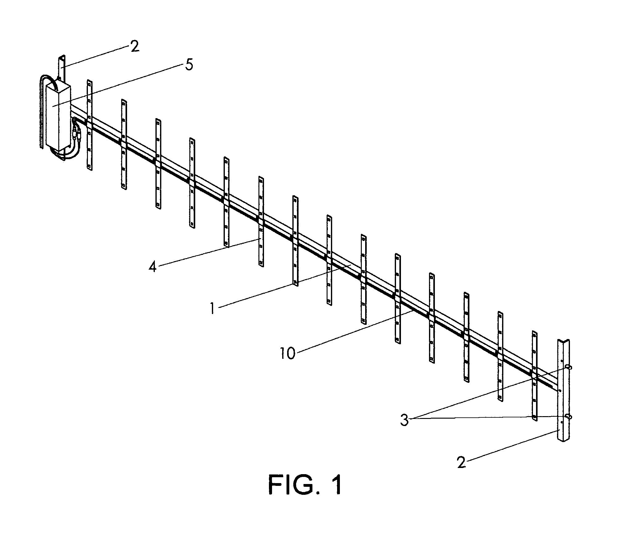
Figure 2 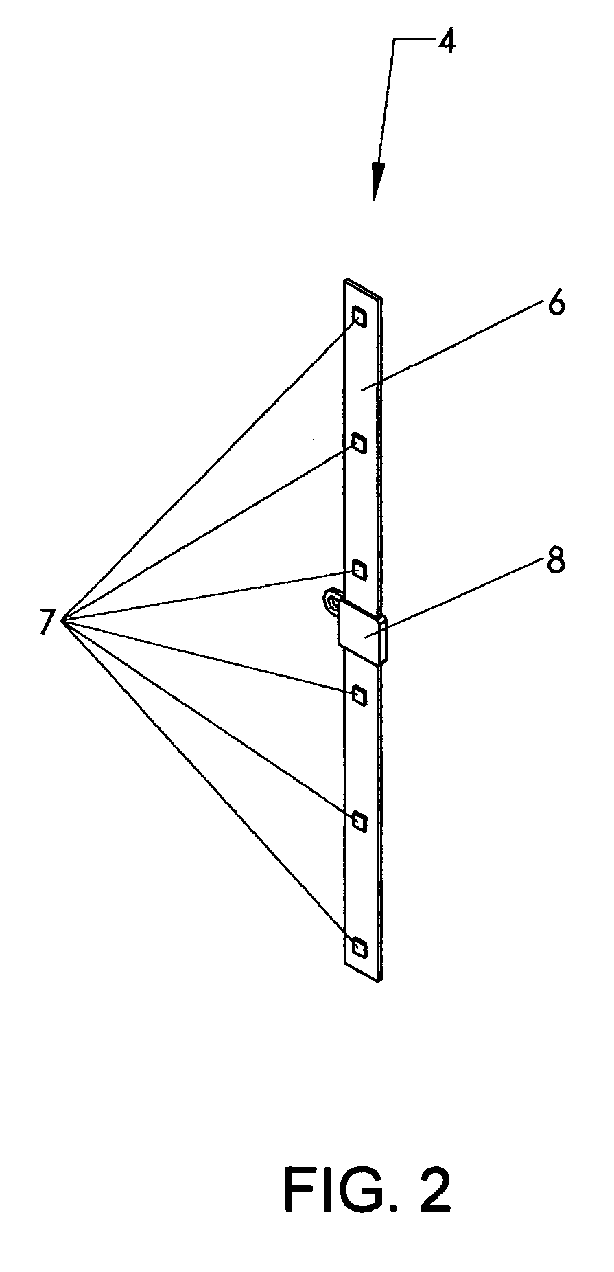
Figure 3
Abstract
Description
FIELD OF THE INVENTIONThe present invention generally relates to a means of easily replacing the fluorescent lighting in backlit signs with longer lasting, lower maintenance, more power efficient light emitting diode modules.BACKGROUND OF THE INVENTIONFluorescent backlit street signs have become the street sign of choice at critical intersections around the world. They make it very easy to identify street names at night, which reduces the level of distraction experienced by drivers unfamiliar with the location. This makes for safer intersections. The downside of these signs with fluorescent lights is they must be replaced approximately every eight months. The cost of the fluorescent tubes themselves is not too great, but the cost of the crew and equipment to perform the maintenance adds up. It is also a nuisance to properly dispose of the spent fluorescent bulbs.It has been recognized that Light Emitting Diodes (LEDs) have the obvious advantage of having a much longer mean life betw...
Examples
Embodiment Construction
The following detailed description is of the best presently contemplated modes of carrying out the invention. This description is not to be taken in a limiting sense, but is made merely for the purposes of illustrating general principles of embodiments of the invention.
FIG. 1 shows assembly typifying an embodiment of the invention tailored to replace two single pin base fluorescent tubes with LED lighting. The frame consists of a long length of extruded aluminum angle 1 to the ends of which are attached two short lengths of extruded aluminum angle 2 using a single fastener such as a pop rivet for each. FIG. 3 shows in greater detail the short length of extruded aluminum angle 2 into which is pressed the single pin base fluorescent tube adapter 3. The entire assembly is pressed into the two sets of fluorescent tube receptacles simultaneously in a manner similar to which the fluorescent tubes are installed. The assembly is now mechanically secured into the fixture. The adapter 3 is ma...