
Pneumatic radial tire for heavy load having lug grooves
a radial tire and lug groove technology, which is applied in the direction of non-skid devices, vehicle components, transportation and packaging, etc., can solve the problems of reducing the amount of rubber of the generating cracks at the groove bottom, and deteriorating wear resistance at the tread surface of the land portion. , to achieve the effect of reducing a bending angle, reducing the slippage of the trailing edge of the other land portion relative to the road surfa
Patent Information
- Authority / Receiving Office
- US · United States
- Patent Type
- Patents(United States)
- Current Assignee / Owner
- Publication Date
- 2015-07-14
- Estimated Expiration
- Not applicable · inactive patent
Smart Images
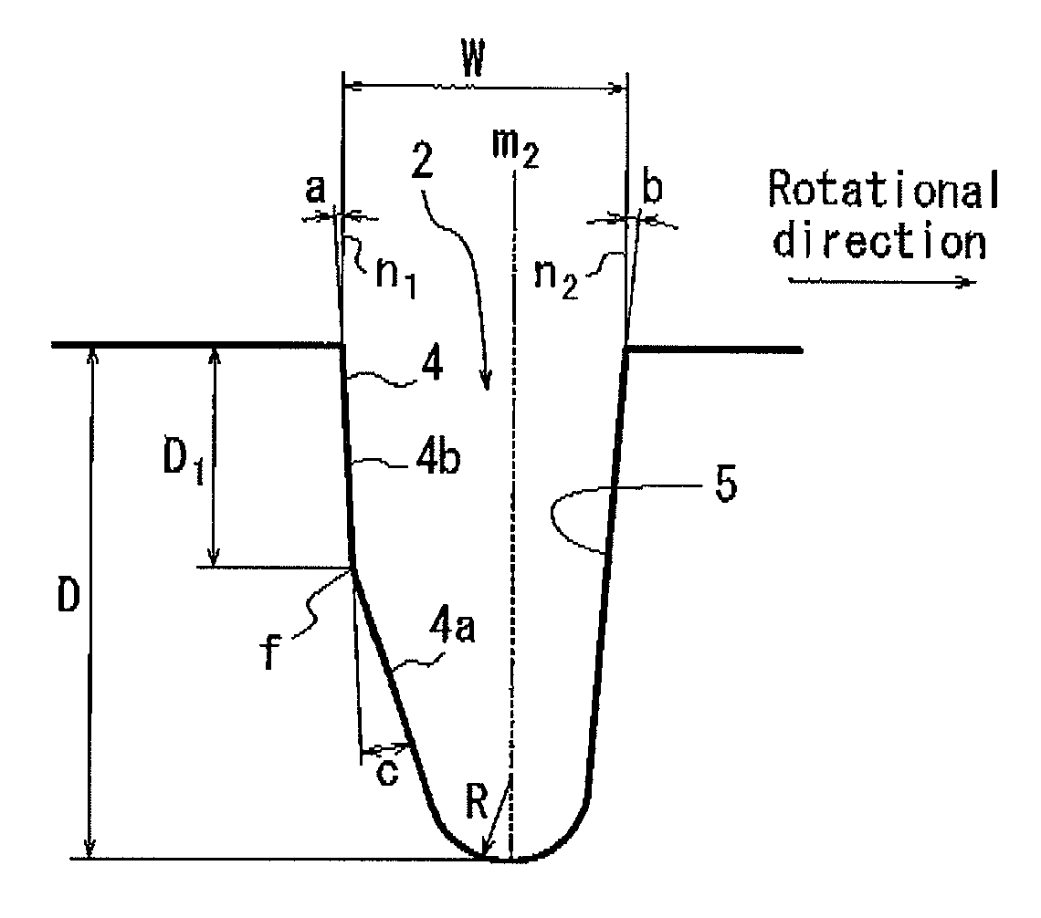
Figure 1 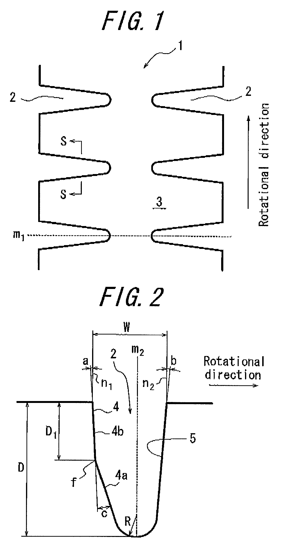
Figure 2 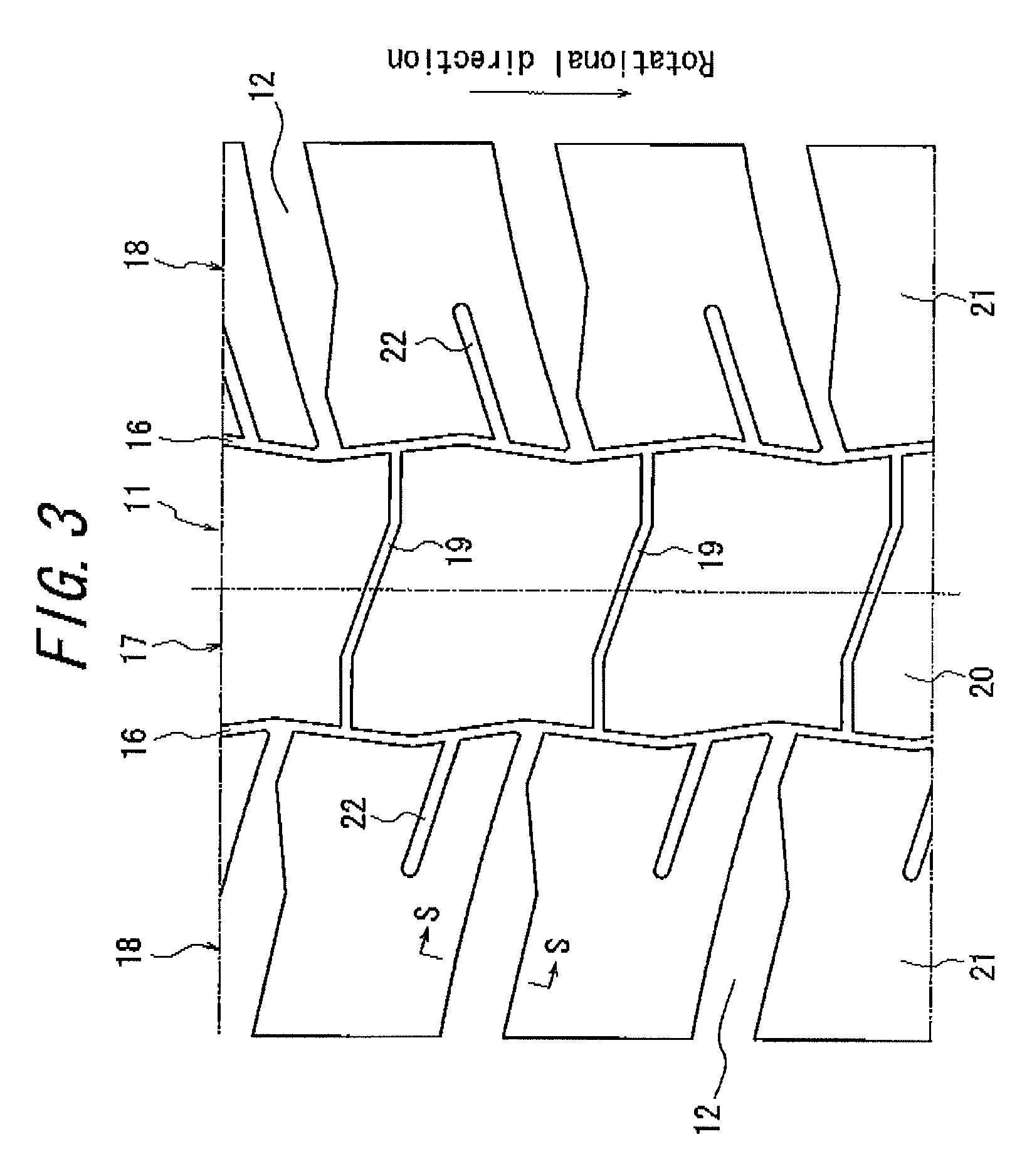
Figure 3
Abstract
Description
TECHNICAL FIELD
[0001] The present invention relates to a pneumatic radial tire for heavy load whose rotational direction is specified, and, in particular, to a pneumatic radial tire possessing improved partial wear resistance at land portions defined by lug grooves in respective side regions of a tread surface thereof.BACKGROUND ART
[0002] In a pneumatic radial tire for heavy load for use in a vehicle such as a construction vehicle adapted to traveling on unpaved roads, there has been widely used a tread pattern having lug grooves in side regions of a tread surface thereof.
[0003] Conventionally, a tire of this type is generally designed such that, in a cross section of a lug groove in the width direction thereof, an angle formed by a groove wall on the step-in side of a land portion, with respect to a line normal to a surface of the land portion, is substantially equal to an angle formed by a groove wall on the kick-out side of the land portion, with respect to a line normal to the surf...
Examples
example 1
[0054]Radial tires with block patterns and size 46 / 90R57 having the structures as shown in FIG. 2 and FIG. 3, respectively, are prepared. An amount of slip of the trailing edge of the block is measured for each of Example tires 1 and 2 according to the present invention and Comparative Example tire, the characteristics of which tires are changed as shown in Table 1.
Comparative Example tire is prepared basically in the same manner as Examples tires because the former requires no modification from the latter, except that a groove wall of a lug groove of the former should have the conventional structure.
[0055]
TABLE 1Example Example Comparative tire 1tire 2Example tirea (°)959b (°)959c (°)9150 D (mm)97.197.197.1D1 (mm)5060—
[0056]Each of Example tires 1 and 2 and Comparative Example tire is assembled with a rim of 1.45 (m)×0.74 (m) (57 (inch)×29 (inch)) and inflated at an internal pressure of 700 kPa. Each tire is rotated with load mass of 62000 kg applied thereon, and an amount of slip ...