
Non-linear resonating sensor and a method
a non-linear resonating sensor and sensor technology, applied in the field of non-linear resonating sensors and methods, can solve the problems of low cost of rfid tags, difficult wired readout, and large potential of wireless sensors, and achieve low cost and complexity of wiring, cost-effectively, and low mass production
Patent Information
- Authority / Receiving Office
- US · United States
- Patent Type
- Patents(United States)
- Current Assignee / Owner
- Publication Date
- 2016-10-25
Smart Images
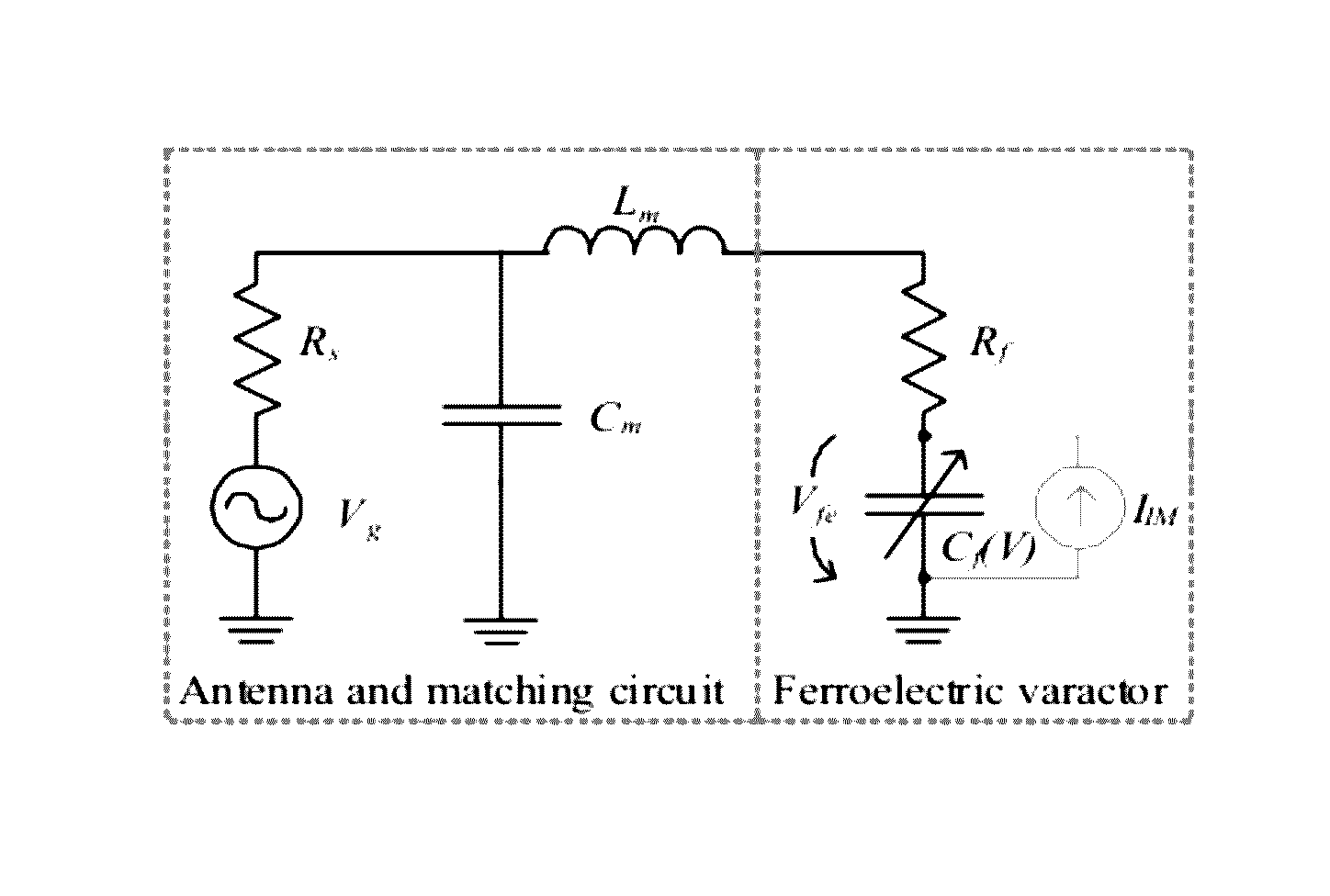
Figure 1 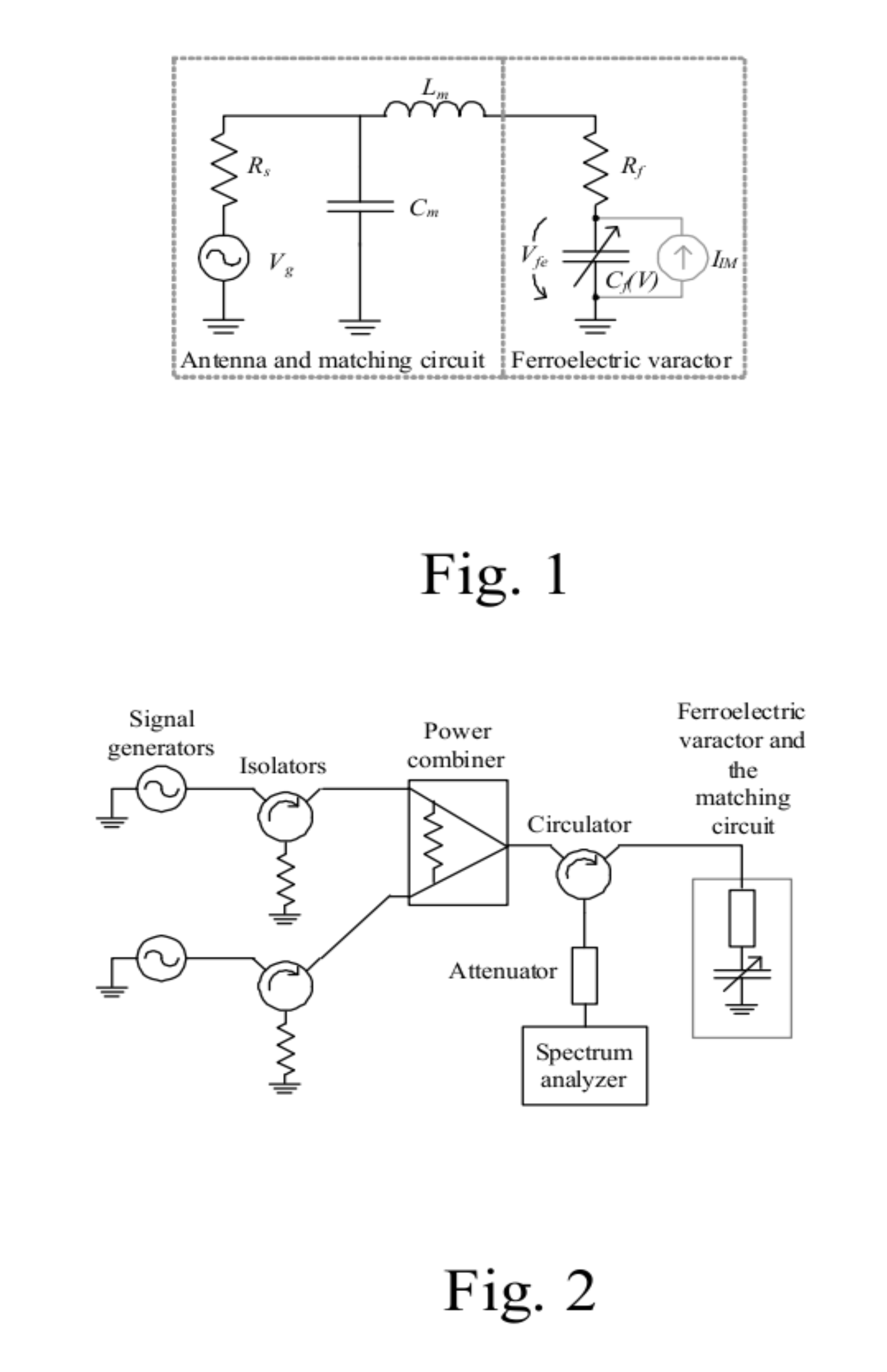
Figure 2 
Figure 3
Abstract
Description
[0001] The present application is a non-provisional application of provisional application 61 / 468,588 filed Mar. 29, 2011 which is herein incorporated by reference in its entirety.BACKGROUND OF THE INVENTION
[0002] Wireless sensors have a great deal of potential in numerous applications where a wired readout is difficult, for example, due to harsh operating conditions, rotating parts or cost and complexity of wiring. Wireless sensors are passive, battery-assisted semi-passive, or active. The advantages of passive sensors are that their life-time or operation conditions are not limited by the battery and that they are inexpensive. Examples of passive wireless sensors are silicon-based radio frequency identification (RFID) tags, surface acoustic wave (SAW) RFID, and inductively-coupled resonance-circuit sensors.
[0003] The RFID tags are based on integrated circuits (ICs), which enable several sophisticated features such as rewritable memory and anti-collision protocols. The cost of an RFID...
Examples
Embodiment Construction
Operation Principle of a Sensor According to an Embodiment of the Present Invention
[0048]The sensor consists, or comprises of a ferroelectric varactor that is conjugate matched to an antenna. The equivalent electrical circuit of the sensor is shown in FIG. 1. The antenna is represented as an equivalent voltage source with the voltage Vg and the internal resistance Rs. The matching circuit consists, comprises, or comprises substantially of the shunt capacitance Cm and the series inductance Lm and may either be included into the antenna or it may be realized as a separate circuit. The resistance Rf represents the losses of the varactor and Cf (V) relates the non-linear capacitance to the voltage. The current source in parallel with the non-linear capacitance is used to represent the modulated current over the varactor in the following analysis.
[0049]The presented sensor can be realized using any non-linear element but the following analysis considers a Barium Strontium Titanate varact...