Cavity filter, filter cavity and installation method of connector

A cavity filter and connector technology, which is applied in the field of radio frequency, can solve the problems of affecting the radio frequency index of the filter, interference, easy water ingress or foreign matter in the gap, so as to improve the waterproof and dustproof performance, close the structure, and avoid signal leakage. Effect

Active Publication Date: 2014-07-30
ANHUI TATFOOK TECH CO LTD
View PDF5 Cites 0 Cited by
  • Summary
  • Abstract
  • Description
  • Claims
  • Application Information

AI Technical Summary

Problems solved by technology

[0005] However, during the research and practice of the prior art, the inventors of the present invention found that, with the above method, there is a gap 109 between the cover plate 106 and the connector 101, and the opening on the top surface of the installation groove cannot be reliably closed. When the signal is transmitted between the connector and the cavity, signal leakage will occur, which will affect the RF index of the filter, and even the leaked signal will cause interference to other equipment in the system, and the gap is prone to water or foreign matter

Method used


Image

  • Cavity filter, filter cavity and installation method of connector
  • Cavity filter, filter cavity and installation method of connector
  • Cavity filter, filter cavity and installation method of connector

Examples


Embodiment 1

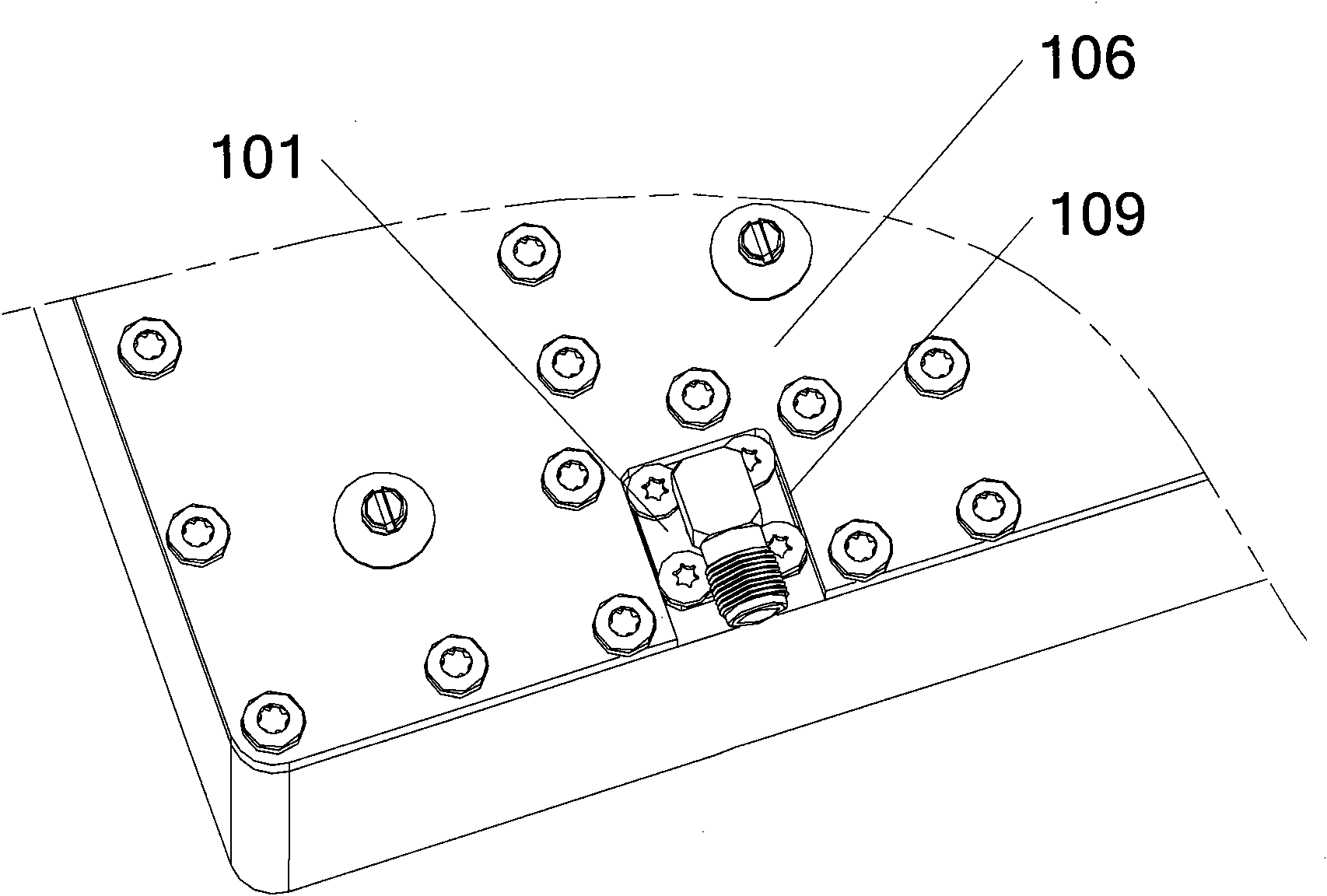
[0023] Embodiment 1, a cavity filter, refer to figure 2 , including: a cavity, a cover plate 206, and a connector 220, and the cover plate 206 is fixed on the top surface of the cavity.

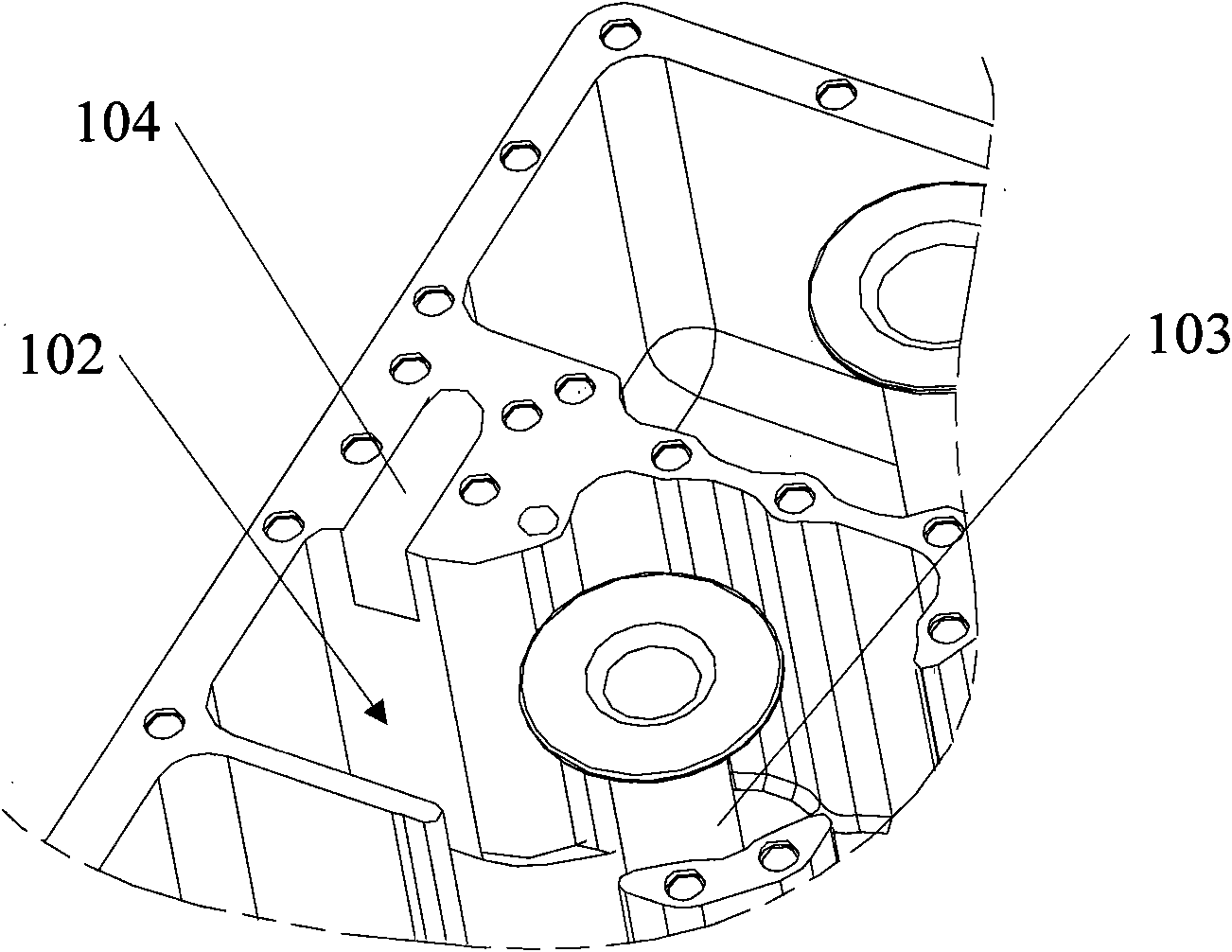
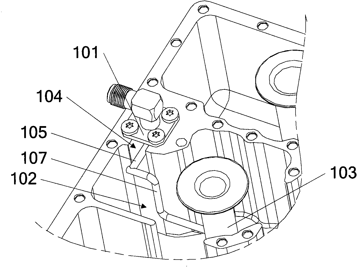
[0024] In the present embodiment, the local structural schematic diagram of the filter cavity is shown in Fig. 3 (a), the cavity includes a side wall 230 of the cavity and an isolation rib 210 that isolates the inside of the cavity into a resonant cavity, and the top surface 211 of the isolation rib A connector installation hole 204 for fixing the connector is provided on the top, and the connector installation hole 204 communicates with the resonant cavity 202 .

[0025] In the present invention, the isolation rib refers to the solid part that isolates the interior of the cavity into a resonant cavity. In order to facilitate the installation of the connector on the top surface of the isolation rib, the part of the isolation rib can be thickened to increase the size of the isolation rib The ...

Embodiment 2

[0036] A cavity filter, reference Figure 4 , including: a cavity, a cover plate, and a connector 420, the cover plate is located on the top surface of the cavity, for the convenience of showing the internal structure of the filter, the cover plate is not shown in the figure, the cavity includes a cavity The side wall 430 of the body and the isolation rib 410 that isolates the interior of the cavity into a resonant cavity, the side wall of the cavity includes the top surface 431 of the side wall of the cavity and the inner surface 432 of the side wall of the cavity, on the top surface 431 of the side wall of the cavity , a connector mounting hole for fixing the connector 420 is provided, and the connector mounting hole communicates with the resonant cavity 402 .

[0037] In this embodiment, an opening 433 is provided on the inner surface 432 of the side wall 430 of the cavity, and the connector mounting hole communicates with the resonant cavity 402 in the cavity through the o...

Embodiment 3

[0041] A filter cavity, comprising a side wall of the cavity and isolation ribs for isolating the inside of the cavity into a resonant cavity, on the top surface of the isolation rib or the top surface of the side wall of the cavity, a connector installation for fixing the connector is arranged hole, and the connector mounting hole communicates with the resonant cavity in the cavity.

[0042] Same as Embodiment 1, in this embodiment, the connector installation hole can be arranged on the top surface of the isolation rib, and an opening is provided on the side of the isolation rib, and the connector installation hole passes through the opening and the cavity. The resonant cavity is connected;

[0043] Same as the second embodiment, the connector mounting hole can also be arranged on the top surface of the side wall of the cavity, and an opening is set on the inner side of the side wall of the cavity, and the connector mounting hole passes through the opening and the inside of t...


PUM


Abstract

The invention discloses a cavity filter, a filter cavity and an installation method of a connector. In the embodiment of the invention, a connector installation hole is arranged on the top surface of an isolation rib or the side wall of the cavity and is communicated with a resonant cavity, and closed regions surround the connector installation hole. After the connector and a cover plate are installed, the resonant cavity and the outside can be reliably isolated, thus avoiding signal leakage and interference of signal leakage with other equipment in the system except the filter.

Description

technical field [0001] The invention relates to the radio frequency field, in particular to a cavity filter, a filter cavity and a method for installing a connector. Background technique [0002] As a frequency selective device, cavity filters are widely used in the field of communication, especially in the field of radio frequency communication. In the base station, the filter is used to select the communication signal and filter out the clutter or interference signal outside the frequency of the communication signal. [0003] The cavity filter includes a cavity, a cover plate, and a connector. The cover plate is located on the top surface of the cavity. The cavity includes side walls of the cavity and isolation ribs that isolate the inside of the cavity into a resonant cavity. The connector is generally installed on the side or bottom of the cavity, and sometimes the connector needs to be installed on the top of the cavity. [0004] In the prior art, the connector is gen...

Claims


Application Information

Patent Timeline
Patent Type & Authority Patents(China)
IPC IPC(8): H01P1/207H01P11/00
Inventor 孙尚传童恩东茹志云
Owner ANHUI TATFOOK TECH CO LTD
Why Eureka
Try Eureka