Finishing machine

A polishing machine and head technology, which is applied in the field of grinding machines, can solve the problems of difficulty in moving, time-consuming replacement of worn belts, and low working efficiency of dust collection devices

Inactive Publication Date: 2011-05-18
艾伦·托马斯·皮克
View PDF5 Cites 9 Cited by
  • Summary
  • Abstract
  • Description
  • Claims
  • Application Information

AI Technical Summary

Problems solved by technology

However, these machines have some drawbacks; the dust collection devices work inefficiently, are difficult to move when they are not running, and it is time consuming to replace worn belts

Method used


Image

  • Finishing machine
  • Finishing machine
  • Finishing machine

Examples


Embodiment Construction

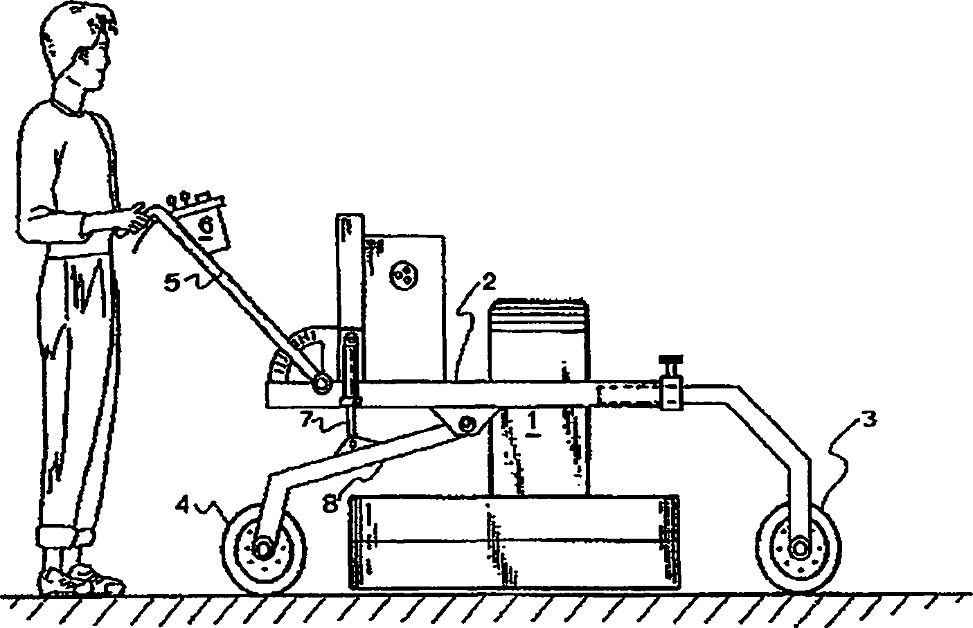
[0017] figure 1 An operator is shown using a polishing machine with a motor 1 mounted on a frame 2 with removable front wheels 3 and adjustable rear wheels 4 . A control box 6 within reach of the operator is installed on the handle 5 . As the machine is turned on and off, the control box 6 controls the height adjustment by operating the hydraulic cylinder 7 to turn the rear wheel strut 8 up or down. Thus, when not in use, the strut 8 is lowered and the machine can be easily pushed to another location.

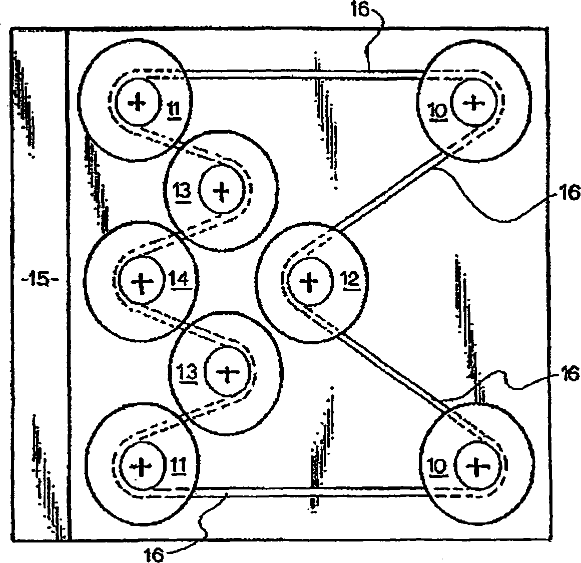
[0018] figure 2 The structure of the grinding head assembly is shown with a pair of assemblies 10 at the front corners, a pair of assemblies 11 at the rear corners, a single assembly 12 in the center, and a pair of assemblies 13 between the center and rear corners. The assembly 14 in the middle of the rear corner does not have a grinding head, but has a fan that pushes the dust into a vacuum manifold 15 located at the rear of the assembly.

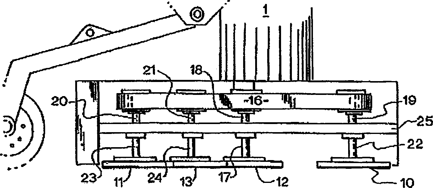
[0019] Motor 1 drives assembly ...


PUM


Abstract

A finishing machine comprises a motor mounted on a support frame and connected to a drive shaft, two or more finishing heads and an impeller fan driven by the drive shaft via a serpentine belt drive which rotates the finishing heads in opposite directions. The impeller fan impels dust from the grinding heads into a rear vacuum manifold and the support frame has rear wheels the height of which is adjustable by means of an hydraulic cylinder.

Description

technical field [0001] The invention relates to a machine for polishing surfaces, such as a grinder for grinding concrete floors. Background technique [0002] US Patent 6,494,772 discloses a ground finishing machine that provides random rotary orbital motion, including a main housing, wheel assembly, handle assembly, motor, belt cover, belt, dust recovery system, and orbital head assembly. The belt drive utilizes a serpentine configuration that turns the head assembly in opposite directions, resulting in reduced torque for easy control and maneuvering of the machine. [0003] Australian patent application 1006202204 discloses a machine also driven by a serpentine belt. The main pulley is driven by a motor and the belt drives the pulley, turning the head assembly in the opposite direction. However, these machines have some drawbacks; the dust collection devices work inefficiently, are difficult to move when they are not running, and replacing worn belts is time consuming. ...

Claims


Application Information

Patent Timeline
Patent Type & Authority Applications(China)
IPC IPC(8): B24B47/10B24B7/18B24B41/047E01C23/088
CPCB24B41/047B24B7/186E04F21/24B24B47/10E04F21/248
Inventor 艾伦·托马斯·皮克
Owner 艾伦·托马斯·皮克
Why Eureka
Try Eureka