Breather

A respirator and breathing tube technology, applied in the field of respirator, can solve the problems affecting the life safety of patients with first aid efficiency, inconvenience of artificial respiration, and the inability of artificial respirator to be inserted into patients, etc., achieving low manufacturing cost, ensuring first aid efficiency, and a simple and compact structure. Effect

Inactive Publication Date: 2014-06-04
岳安山
View PDF0 Cites 3 Cited by
  • Summary
  • Abstract
  • Description
  • Claims
  • Application Information

AI Technical Summary

Benefits of technology

This patented device helps people who have trouble breathing without having their teeth blocked up or being bitten off during sleeping hours when they don’t want them outdoors due to lack of oxygenation. It works well even if there aren′t enough space between your teeth.

Problems solved by technology

The technical problem addressed by this patented technology is that current artificial respirs have issues with biting or closing teeth due to their design causing difficulties for dentists who want them to perform effective treatment while still being able to insert it safely through an opening on one side (mouth).

Method used


Image

  • Breather
  • Breather

Examples


Embodiment Construction

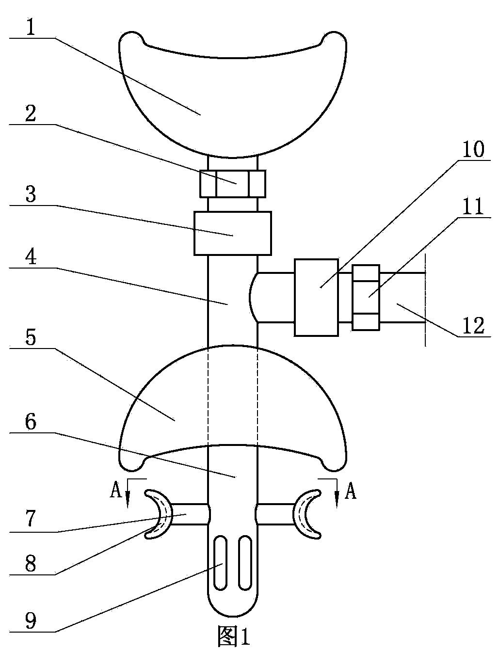
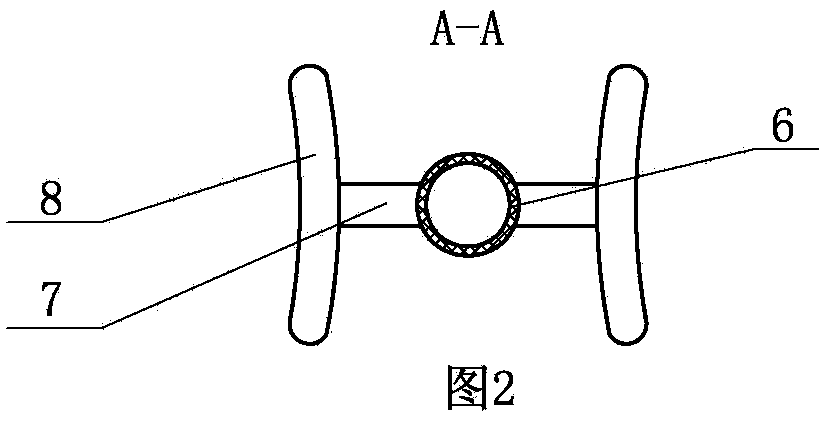
[0009] A kind of respirator of the present invention, as figure 1 Shown, comprise breathing tube 4, breathing tube 4 is covered with lower breathing cover 5, and breathing tube 4 lower ends offer several through holes 9; figure 2 As shown, two support frames 7 are symmetrically fixedly installed on the breathing tube 4 of the lower part of the lower breathing mask 5, and an oral cavity expansion frame 8 is fixedly installed on each support frame 7. The peripheral shape of the expansion frame 8 in the oral cavity is consistent with the profile of people's teeth match. During use, the breathing tube 4 below the lower breathing cover 5 is inserted in the patient's mouth, and the patient's oral cavity is buckled by the lower breathing cover 5 to prevent air leakage. For a patient who is severely comatose due to a critical condition, and the teeth are too tightly occluded, the patient's jaw can be pried open, and the present invention is placed in the patient's mouth, so that the...


PUM


Abstract

The invention provides a breather. The breather comprises a breathing tube sleeved with a lower respirator, wherein the lower end of the breathing tube is provided with a plurality of through holes, two supporting frames are fixedly and symmetrically installed at the position, at the lower end of the lower respirator, of the breathing tube, each supporting frame is fixedly provided with an oral cavity expanding frame, the shape of the periphery of each oral cavity expanding frame is matched with the outline of teeth of a person, and an upper respirator is installed at the upper end of the breathing tube. The breather can be placed in the pried-open mandibular joints of a patient with tight dental occlusion and in a severe coma, the mandibular joints can be prevented from being closed automatically, and thus the artificial breather can be inserted into the mouth of the patient, and emergency treatment efficiency is guaranteed.

Description


Claims


Application Information

Patent Timeline
Owner 岳安山
Why Eureka
Try Eureka