sunshade device

A sunshade, assembly position technology, applied in the direction of transportation and packaging, roofing, vehicle parts, etc., can solve problems such as shrinkage

Inactive Publication Date: 2016-11-23
TOYOTA JIDOSHA KK
View PDF8 Cites 0 Cited by
  • Summary
  • Abstract
  • Description
  • Claims
  • Application Information

AI Technical Summary

Problems solved by technology

[0003] However, since the displacement of the visor in the width direction after assembly is not restricted when set in such a manner, there is a possibility that shrinkage occurs at the bracket side portion of the visor when an external force acts on the visor.

Method used


Image

  • sunshade device
  • sunshade device
  • sunshade device

Examples


no. 1 approach ]

[0018] use Figure 1 ~ Figure 3 , the sunshade device according to the first embodiment of the present invention will be described. In addition, in the following description, the side indicated by the arrow UP in the figure is referred to as the upper side for convenience of description, but this does not limit the application direction of the sunshade device with respect to the vehicle body.

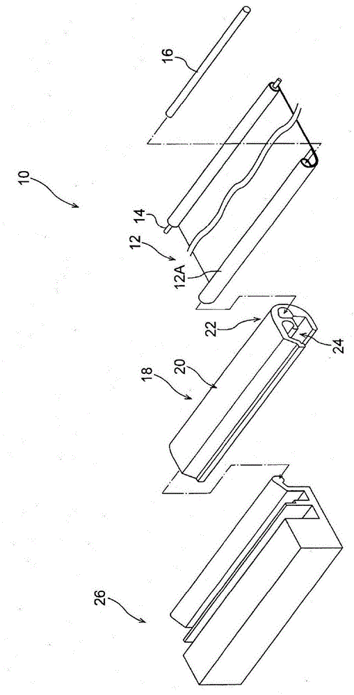
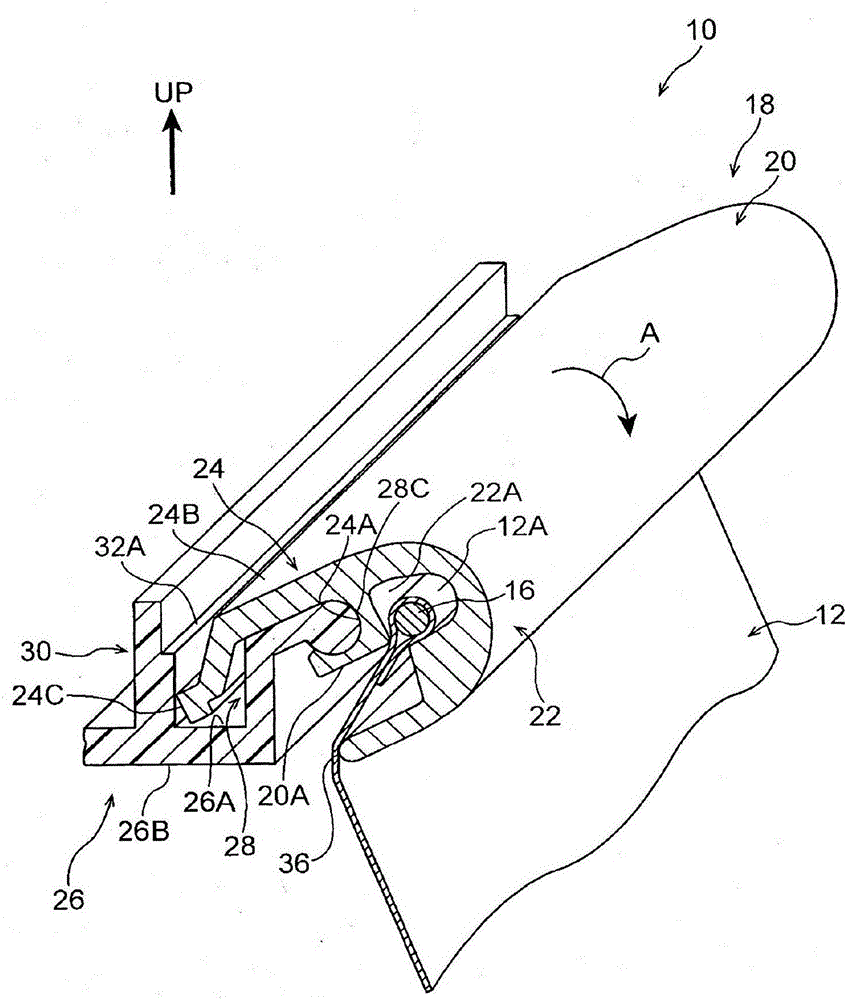
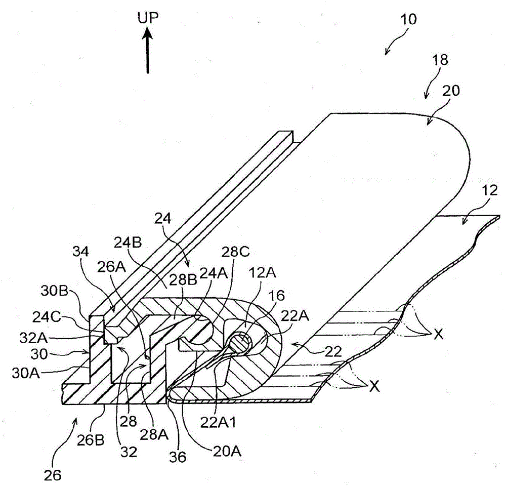
[0019] exist figure 1 Here, the main part of the sunshade device 10 according to this embodiment is shown by an exploded perspective view. In addition, in figure 2 In , the state in the middle of the assembly of the sunshade device 10 is represented by a half-section perspective view, in image 3 In , the final assembled state of the sunshade device 10 is represented by a perspective view in half section. The sunshade device 10 shown in these figures is disposed at, for example, an opening of a vehicle body (an opening of a roof as an example) that is closed with glass or the like....

no. 2 approach ]

[0043] Next, use Figure 4 as well as Figure 5 , the sunshade device according to the second embodiment of the present invention will be described. exist Figure 4 In this embodiment, the sunshade device 40 according to this embodiment is a half-sectional perspective view of a state in the middle of assembly (equivalent to the first embodiment) figure 2 Figure) representation. In addition, in Figure 5 In the final assembly state of the sunshade device 40, the perspective view of the half section (equivalent to the first embodiment image 3 Figure) representation.

[0044] As shown in these figures, the sunshade device 40 is equipped with a replacement bracket 18 (refer to Figure 1 ~ Figure 3 ) of the bracket 42, and has a replacement handle 26 (refer to Figure 1 ~ Figure 3 ) and the handle 50 (in a broad sense, an element grasped as a "holding member") as a base member is different from the first embodiment. The other structures are the same as those of the first ...


PUM


Abstract

A sunshade device. The base member (26) is configured so that the bracket main body (20) can surround the bracket main body (20) The shaft is supported in such a way that it rotates toward the assembly position of the bracket main body. The locking mechanism (34) restricts the rotation of the bracket main body from the mounting position in a state where the bracket main body is arranged at the mounting position. In addition, the fastening part ( 36 ) integrally formed with the bracket body part 20 can sandwich the visor ( 12 ) between the bracket body part and the base member in a state where the bracket body part is arranged at the mounting position. way to fix the visor.

Description

technical field [0001] The invention relates to a sunshade device. Background technique [0002] In the sunshade device, there is known a structure in which one end side of the sunshield can be rolled up and pulled out, and the other end of the sunshield is accommodated in the bracket (for example, refer to International Publication No. 2010 / 106767 ). However, when assembling such a sunshade device, after the other end of the visor is accommodated in the bracket, the bracket may slide from the side of the handle along the length direction of the handle through the bracket. guide so that the bracket is fitted on the handle. In addition, at this time, the distance between the opening formed by the bracket and the handle is set to be larger than the thickness of the visor so that the visor does not get caught between the bracket and the handle. [0003] However, since the displacement of the visor in the width direction after assembly is not restricted when set in such a man...

Claims


Application Information

Patent Timeline
Patent Type & Authority Patents(China)
IPC IPC(8): B60J7/00
Inventor 后藤刚
Owner TOYOTA JIDOSHA KK
Why Eureka
Try Eureka