Rotating lever rotating reset mechanism

A technology of reset mechanism and rotating rod, which is applied to steering mechanisms, motor vehicles, bicycle accessories, etc., can solve the problems of inability to guarantee reset accuracy, large weight and volume, and reduced reset torque, and achieves light weight, compact structure, and reduced reset. effect of noise

Inactive Publication Date: 2016-03-16
SHANGHAI NEW CENTURY ROBOT
View PDF10 Cites 0 Cited by
  • Summary
  • Abstract
  • Description
  • Claims
  • Application Information

AI Technical Summary

Problems solved by technology

Among the existing reset mechanisms, one is to use rubber to provide torque to achieve reset, which is relatively large in weight and volume, and the other is to use steel plate bending to provide reset torque. Since the steel plate is easy to wear, the reset torque tends to decrease day by day. , reset accuracy cannot be guaranteed

Method used


Image

  • Rotating lever rotating reset mechanism
  • Rotating lever rotating reset mechanism
  • Rotating lever rotating reset mechanism

Examples


Embodiment Construction

[0015] The present invention will be further described below in conjunction with the accompanying drawings.

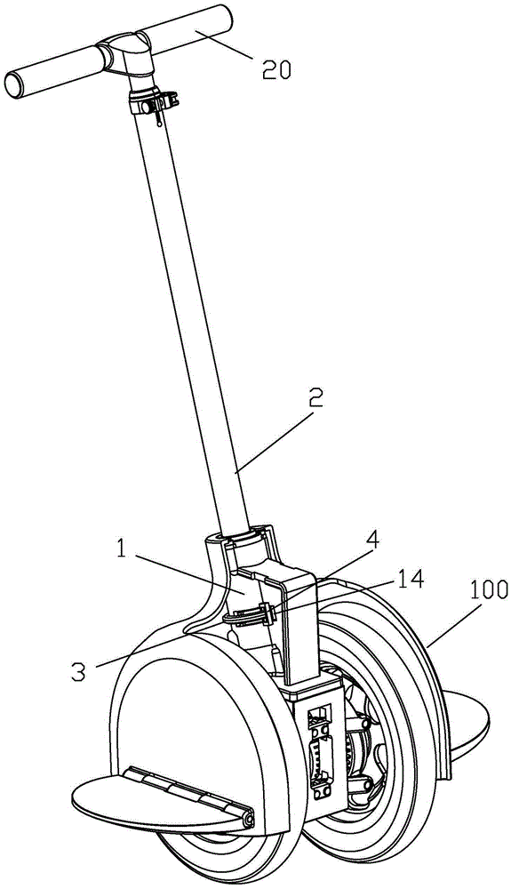
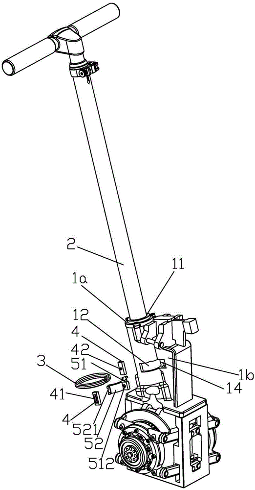
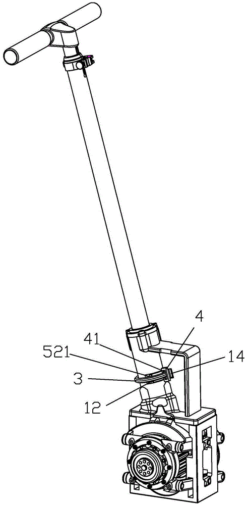
[0016] see Figure 1 to Figure 5 . According to an embodiment of the present invention, the rotation reset mechanism of the rotating rod includes a rod seat 1, a rotating rod 2, a C-shaped spring 3, a pair of pressing blocks 4 and a spring holding mechanism.

[0017] The pole base 1 includes a base portion 1a and a side plate portion 1b. The base part 1a is substantially cylindrical, and has a central hole 11 extending in the axial direction, and a guide groove 12 extending in the circumferential direction is formed on the side wall of the base part 1a. One side of the side plate portion 1 b is connected to the base portion 1 a and perpendicularly intersects with the guide groove 12 , and a notch 14 is formed at a position intersecting with the guide groove 12 on one side of the side plate portion 1 b.

[0018] The rotating rod 2 is the joystick of the self-balancin...


PUM


Abstract

The invention discloses a rotation reset mechanism of a rotating rod. The mechanism comprises a rod seat, a rotating rod, a C-shaped spring, a spring holding mechanism and a pair of pressing blocks, wherein the rod seat comprises a base seat part and a side plate part; a center hole is formed in the base seat part, and a guide groove which extends along the circumference is formed in the side wall of the base seat part; one side of the side plate part is connected with the base seat part and is perpendicular to and intersected with the guide groove, and a gap is formed in one side of the side plate part at the position where the side plate part is intersected with the guide groove. The first end part of the rotating rod is inserted into the center hole; a guide bump is arranged on the side wall of the rotating rod, and the guide bump extends outside the guide groove and can move along the guide groove. The C-shaped spring is around the base seat part, and the pressing blocks are respectively fixed at both ends of the C-shaped spring and are positioned on both sides of the guide bump. When the rotating rod is in an initial position, the guide bump extends into the gap of the side plate part; and the pressing blocks are tightly attached to the two relative side surfaces of the guide bump. The mechanism has the advantages of simple and compact structure, light weight and high reset precision.

Description

technical field [0001] The invention relates to a rotary reset mechanism of a rotary rod. Background technique [0002] The structure and working principle of the steering device of a common self-balancing two-wheeled electric vehicle are as follows: the steering rod for manipulation is erected on the rod seat, and the operator drives the handle arranged on the upper end of the rotating rod to move forward through the operation of the hand or leg when steering. Rotate clockwise or counterclockwise, and then drive the rotating rod connected to the handle to rotate clockwise or counterclockwise around the central axis of the rotating rod from the initial position, detect the rotation angle of the rotating shaft through the detection device, and The detection signal reflecting the variation of the rotation angle is sent to the control system of the self-balancing two-wheeled electric vehicle, thereby controlling the steering of the self-balancing two-wheeled electric vehicle. ...

Claims


Application Information

Patent Timeline
Patent Type & Authority Patents(China)
IPC IPC(8): B62K21/10B62K11/00
Inventor 沈林方继勇陈养彬
Owner SHANGHAI NEW CENTURY ROBOT
Why Eureka
Try Eureka