A coiled tubing velocity string and a method for liquid drainage and gas recovery

A velocity string and tubing technology, which is applied to the coiled tubing velocity string and drainage and gas production fields, can solve the problems of slow processing speed, inability to effectively solve gas well production problems, and long coiled tubing length.

Active Publication Date: 2017-01-04
JEREH ENERGY SERVICES
View PDF5 Cites 4 Cited by
  • Summary
  • Abstract
  • Description
  • Claims
  • Application Information

AI Technical Summary

Problems solved by technology

Conventional coiled tubing velocity strings hang the coiled tubing at the wellhead, which requires a long length of coiled tubing. Since the processing period of the coiled tubing is limited by the domestic processing level, the processing speed is relatively slow, resulting in the production problem of the gas well cannot be effectively solved

Method used


Image

  • A coiled tubing velocity string and a method for liquid drainage and gas recovery
  • A coiled tubing velocity string and a method for liquid drainage and gas recovery
  • A coiled tubing velocity string and a method for liquid drainage and gas recovery

Examples


Embodiment Construction

[0052] The invention discloses a coiled tubing velocity string, which can shorten the service length of the coiled tubing and ensure the timely solution to the production problem of the gas well. The invention also discloses a method for liquid drainage and gas recovery of a coiled tubing velocity string.

[0053] The following will clearly and completely describe the technical solutions in the embodiments of the present invention with reference to the accompanying drawings in the embodiments of the present invention. Obviously, the described embodiments are only some, not all, embodiments of the present invention. Based on the embodiments of the present invention, all other embodiments obtained by persons of ordinary skill in the art without making creative efforts belong to the protection scope of the present invention.

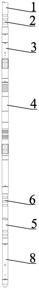
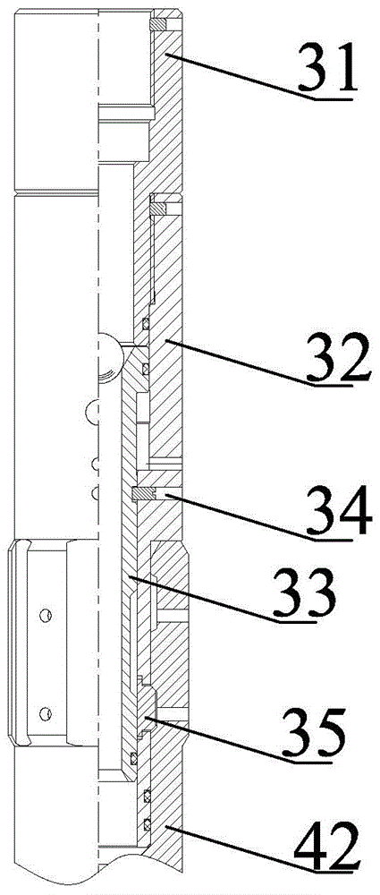
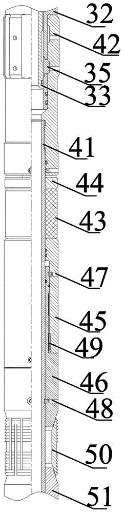
[0054] see Figure 1-Figure 4 , figure 1 Schematic diagram of the structure of the coiled tubing velocity string provided by the embodiment of the presen...


PUM


Abstract

A coiled tubing velocity string that can be lowered to a predetermined position by a coiled tubing equipment. A blanking plug (8) blocks the end of a second coiled tubing (5). A hanger (4) is set and liquid is pumped into the annular space formed by an oil tubing and the coiled tubing velocity string to check the seating effect. The blanking plug (8) is pulled out so that the coiled tubing velocity string is communicated with the annular space formed by the oil tubing and the second coiled tubing (5). A hydraulic releasing tool (3) releases the hanger (4), then a first coiled tubing (1), a first coiled tubing joint (2) and the hydraulic releasing tool (3) are lifted by the coiled tubing equipment after the release operation is completed, and production begins. Compared to the mode of hanging the coiled tubing velocity string at a wellhead in the prior art, the coiled tubing velocity string is set in the specified position by the equipment, reducing the length of the coiled tubing used and solving the problem that the problem of a gas well caused by non-timely supply of the coiled tubing can not be solved in time.

Description

technical field [0001] The invention relates to the technical field of petroleum engineering, in particular to a coiled tubing velocity string and a method for liquid drainage and gas recovery. Background technique [0002] The gas well enters the middle and late stages of production. Due to the drop in gas layer pressure, the water volume in the low-pressure well increases, the liquid carrying capacity of the gas becomes poor, and the wellbore fluid accumulation increases, which affects the normal production of the gas well and even shuts down. In the prior art, the velocity tube is generally used The column drainage gas recovery technology improves the liquid-carrying capacity of the gas and restores the gas well to a state of stable production. [0003] The coiled tubing velocity string suspended in the tubing is composed of coiled tubing, coiled tubing joint, hydraulic hand, velocity string hanger and plug. Conventional coiled tubing velocity strings hang coiled tubing ...

Claims


Application Information

Patent Timeline
Patent Type & Authority Patents(China)
IPC IPC(8): E21B17/00E21B23/01E21B23/10E21B33/127E21B33/129
CPCE21B17/00E21B23/01E21B23/10E21B33/127E21B33/129
Inventor 宁世品叶登胜梅鹏
Owner JEREH ENERGY SERVICES
Why Eureka
Try Eureka