Electrical cabinet door lock

A technology for electrical cabinets and door locks, applied in construction locks, door/window accessories, non-mechanical transmission-operated locks, etc., can solve the problems of no significant improvement in anti-theft performance, inconvenient installation and use, complex structure, etc., and achieve strong anti-theft performance , Easy operation and compact structure

Inactive Publication Date: 2016-10-26
ZHEJIANG ZHONGZHENG LOCK CO LTD
View PDF6 Cites 2 Cited by
  • Summary
  • Abstract
  • Description
  • Claims
  • Application Information

AI Technical Summary

Problems solved by technology

[0003] In order to overcome the problems in the prior art that the electromagnetic control and mechanical control of the ordinary electrical cabinet door lock can only be used alone, the anti-theft performance has not been significantly improved, the structure is too complicated, the reliability is low, and the installation and use are relatively inconvenient. Provided is an electric cabinet door lock, which has a compact structure, convenient operation and use, strong anti-theft performance and high reliability

Method used


Image

  • Electrical cabinet door lock
  • Electrical cabinet door lock
  • Electrical cabinet door lock

Examples


Embodiment Construction

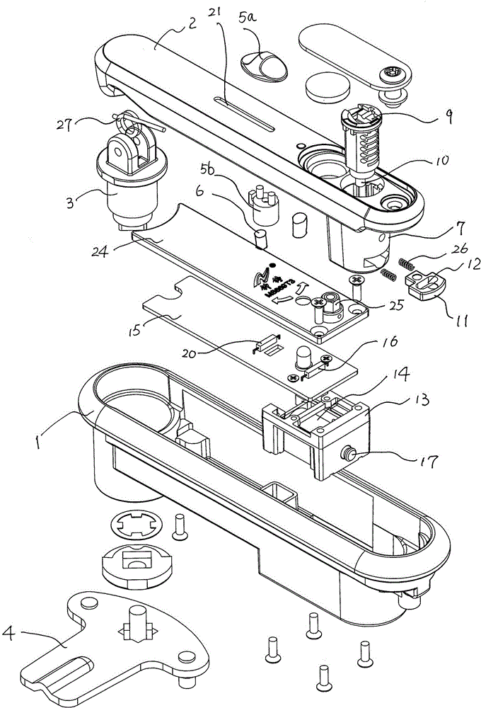
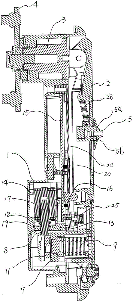
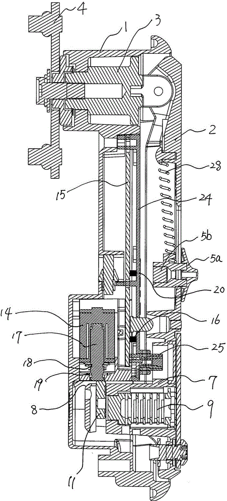
[0014] As shown in the figure, the present invention includes a lock body 1, a handle 2, a lock shaft 3 and a door lock 4. The upper end of the handle 2 is hinged on one end of the lock shaft 3, and the other end of the lock shaft 3 is connected to the door lock 4. The handle 2 drives the door leaf lock to move through the lock shaft 3. The handle 2 is provided with a sliding trigger switch 5, a magnetic block 6 and a protruding locking part 7. The corner of the lower end of the locking part 7 is formed as a pushing part 8. Lock core 9 is installed in locking part 7, and the bottom of lock core 9 is eccentrically provided with driving lever 10, and driving lever 10 is connected with sliding locking piece 11 through long groove 12 on the sliding locking piece 11, and sliding locking piece 11 in locking part 7 A second return spring 26 is provided on one side. In the lock body 1, a coil support 13 is arranged on one side of the locking part 7, and the electromagnetic coil 14 and...


PUM


Abstract

The invention relates to an electrical cabinet door lock. The electrical cabinet door lock comprises a lock body, a handle, a lock shaft and a door leaf locking piece. A sliding trigger switch, a magnetic block and a protruding locking portion are arranged on the handle. A push and press portion is formed at the corner of the lower end of the locking portion. A lock cylinder is installed in the locking portion. A shifting lever is arranged at the bottom of the lock cylinder eccentrically and connected with a sliding lock plate through a long slot in the sliding lock plate. A coil support is arranged in the lock body and located on one side of the locking portion. An electromagnetic coil and a circuit board are fixed to the coil support. The circuit board is provided with a trigger switch sensor and a handle sensor, wherein the trigger switch sensor is matched with the sliding trigger switch, and the handle sensor is matched with the magnetic block. A sliding lock pin is located and installed in the electromagnetic coil in a sliding manner. The sliding lock pin is sleeved with a first reset spring. The first reset spring is located between the electromagnetic coil and a locating sheet fixed to the sliding lock pin in the radial direction in an abutting manner. One end of the sliding lock pin is matched with the sliding lock plate. The electrical cabinet door lock has the beneficial effects of being compact in structure, convenient to operate and use, high in anti-theft performance and high in reliability.

Description

technical field [0001] The invention relates to an electric cabinet door lock. Background technique [0002] In order to improve the anti-theft performance of locks, locks using electromagnetic and mechanical dual control have appeared in the prior art, but the electromagnetic control and mechanical control of the above-mentioned locks can only be used alone, the anti-theft performance has not been significantly improved, and its structure is too complicated , low reliability, and inconvenient installation and use. Contents of the invention [0003] In order to overcome the problems in the prior art that the electromagnetic control and mechanical control of the ordinary electrical cabinet door lock can only be used alone, the anti-theft performance has not been significantly improved, the structure is too complicated, the reliability is low, and the installation and use are relatively inconvenient. Provided is an electric cabinet door lock, which has a compact structure, ...

Claims


Application Information

Patent Timeline
Patent Type & Authority Applications(China)
IPC IPC(8): E05B65/52E05B3/00E05B15/00E05B47/00
CPCE05B65/5223E05B3/00E05B15/00E05B47/0002
Inventor 陈成忠
Owner ZHEJIANG ZHONGZHENG LOCK CO LTD
Why Eureka
Try Eureka