driving force receiver

A driving force and component technology, which is applied in the field of processing boxes, can solve the problems of incomplete drop-off, poor compatibility, and jamming of the driving head, and achieve the effect of stable driving force transmission.

Active Publication Date: 2019-03-15
ZHUHAI UN TERN IMAGING PROD
View PDF4 Cites 0 Cited by
  • Summary
  • Abstract
  • Description
  • Claims
  • Application Information

AI Technical Summary

Problems solved by technology

[0004] The method of using the swing rod to assist the telescopic method or the main machine door cover to assist the push of the swing rod depends on the structure of the machine, the compatibility is not good, and there is a problem that the machine is not in place or it is difficult to take it out; There are problems such as slippage caused by the failure of the drive parts to mesh with the drive head of the main engine when turning in at certain angles when landing
Moreover, no matter it is a process box that adopts a pendulum-assisted telescopic mode or a main machine door cover that assists in pushing the pendulum, or a process box that is created and dismantled by force, the drive head must be in contact with the drive during the process of loading / unloading the process box. The drive claws of the force receiving component are in contact. If the position is not appropriate, there will be problems such as the drive claw of the drive force receiving component meshing with the drive head of the main engine, etc.

Method used


Image

  • driving force receiver
  • driving force receiver
  • driving force receiver

Examples


Embodiment 1

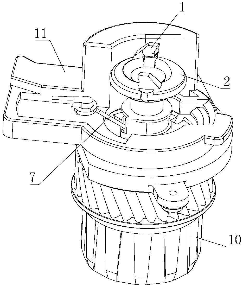
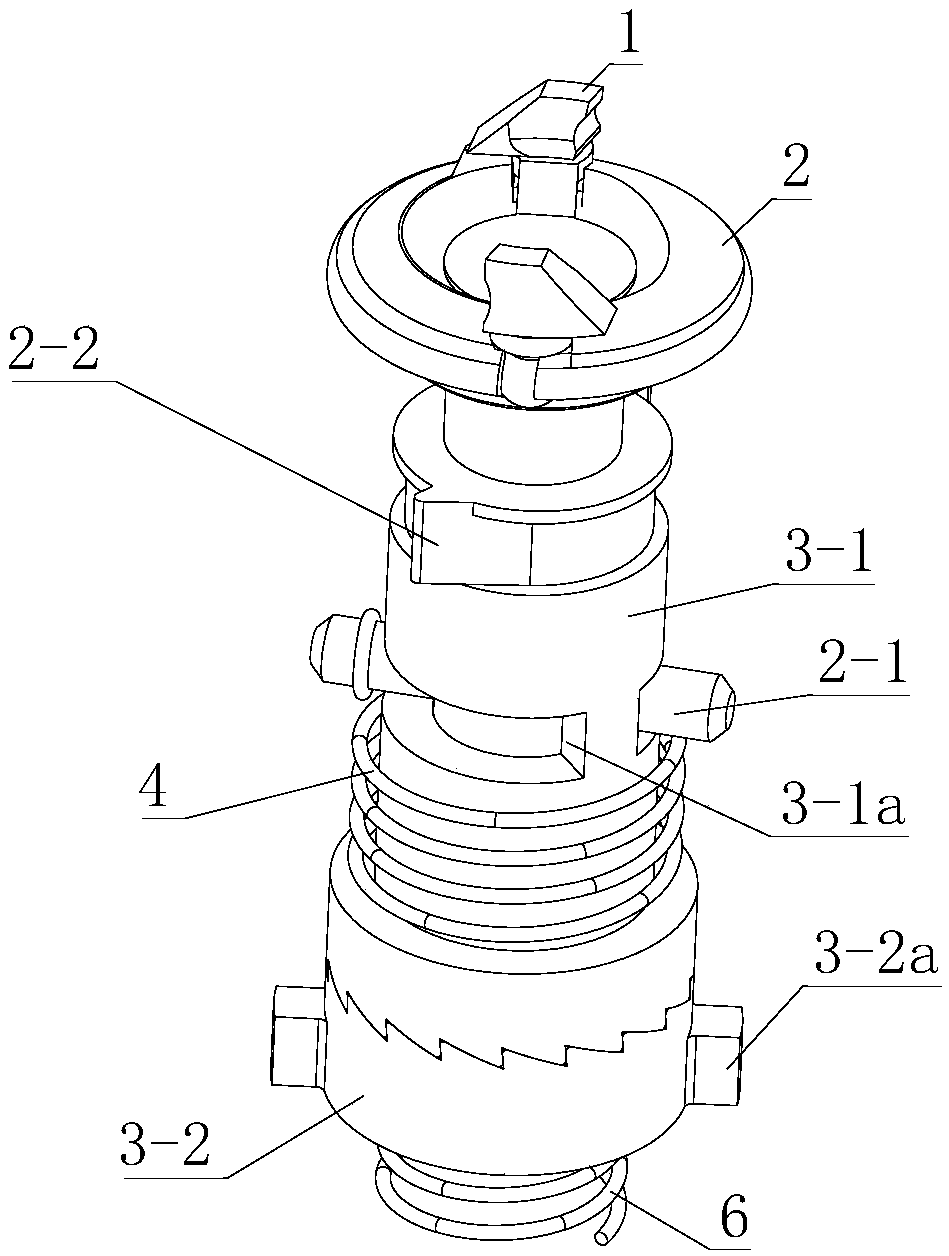
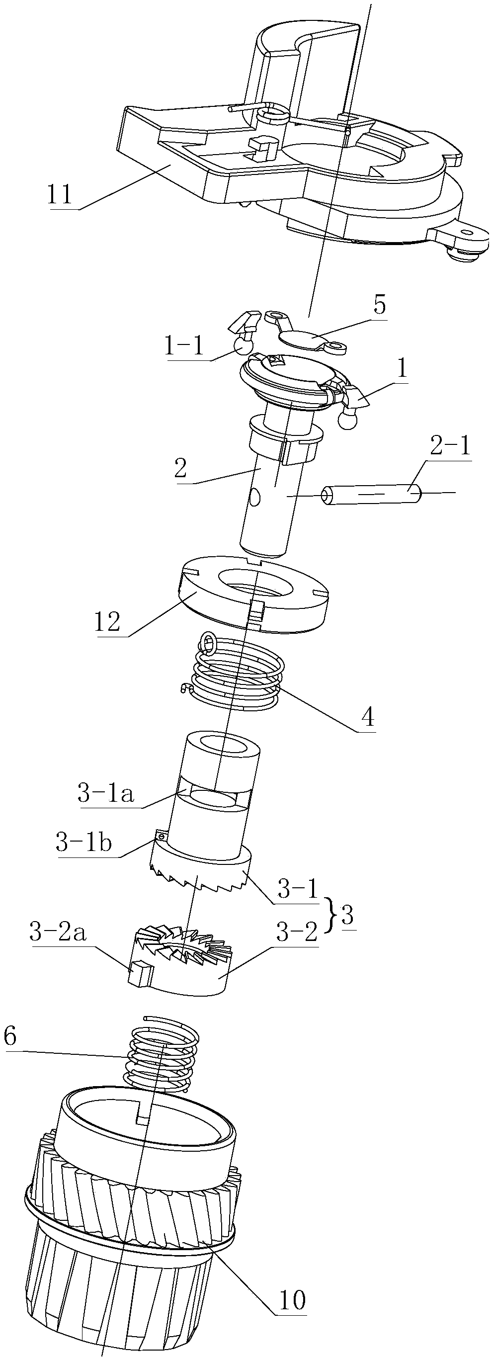
[0038] The driving force receiving assembly is used to receive the rotational force of the drive head in the image forming device, and transmit the rotational force to the photosensitive drum to drive the photosensitive drum to rotate. other rotating parts in the box. Such as figure 1 , figure 2 and image 3 As shown, the driving force receiving assembly of the present invention includes two symmetrically arranged power receiving parts 1 , a power transmission part 2 , a driving matching part 3 and a position adjusting device. The driving matching part 3 of this embodiment is a split structure, which includes a first fitting part 3-1 matching with the power transmission part 2 and a second fitting part 3-2 matching with the photosensitive drum. The second fitting part 3-2 of this embodiment The assembly part 3-2 cooperates with the input gear 10 arranged at the end of the photosensitive drum, but the second assembly part 3-2 can also directly cooperate with the photosensit...

Embodiment 2

[0052] Such as Figure 9 as shown, Figure 9 The direction indicated by the middle arrow is the predetermined rotational driving direction. The difference between this embodiment and Embodiment 1 is that the limit adjustment device 7 of this embodiment is an elastic swing arm with one end fixed on the gear end cover 11, and the elastic swing arm is made of elastic materials, such as metal shrapnel or Rubber body etc. The power transmission part 2 is provided with a stop protrusion 2-2 protruding from its outer wall. The cross-sectional shape of the stop protrusion 2-2 in this embodiment along the direction perpendicular to the axis of the power transmission part is trapezoidal, but it can also be rectangular . The included angle between the axis a2 of the elastic swing arm and the line a3 between the center point of the limiting protrusion and the rotation centerline of the power transmission part along the rotation direction of the power transmission part is greater than 0...

Embodiment 3

[0054] Such as Figure 10 as shown, Figure 10The direction indicated by the middle arrow is the predetermined rotational driving direction. The difference between this embodiment and the second embodiment is that the limit adjustment device includes a rotating swing arm 7 and an elastic member 7a. The rotating swing arm is hinged on the gear end cover 11 and can rotate around the hinge point. The elastic member 7a is arranged on Between the rotating swing arm and the side wall of the gear end cover, they are respectively connected with the rotating swing arm and the side wall of the gear end cover. The included angle between the axis of the rotating swing arm, the center point of the limit protrusion and the rotation centerline of the power transmission part along the rotation direction of the power transmission part is greater than 0 degrees and less than 90 degrees. During the rotation of the power transmission part 2, when the limit protrusion 2-2 passes the rotating swi...


PUM


Abstract

The invention discloses a driving force receiving assembly for receiving the rotating force of the driving head of an image forming device and transmitting the rotating force to a photosensitive drum so as to drive the photosensitive drum to rotate. The driving force receiving assembly comprises at least two symmetrically arranged power receiving parts, a driving matching part and a power transmission part, wherein the at least two symmetrically arranged power receiving parts are engaged with an engaging part of the driving head of the image forming device; the driving matching part is matched with the photosensitive drum; and the power transmission part is connected to the power receiving part and the driving matching part. According to the driving force receiving assembly, the two symmetrically arranged power receiving parts are engaged with the driving head in the manner that the minimum value L of the length of a connecting line between any two points in a projection area on a plane in the direction vertical to the installation direction of a processing cartridge meets the formula that L is greater than or equal to D / 2 and smaller than or equal to D+H, wherein D is the maximum outer diameter of the driving head vertical to the rotation axis of the driving head, and H is the height of the outermost point of a contour surface of the driving head, extruding out of an engaging part installation position, of the engaging part of the driving head. According to the driving force receiving assembly, driving force transmission can be realized stably and reliably, and the smooth falling / taking of the processing cartridge can be guaranteed.

Description

technical field [0001] The present invention relates to a process cartridge having a photosensitive drum used in a laser printer, copier or facsimile machine, and more particularly, to a driving force receiving assembly used on the photosensitive drum in the process cartridge. Background technique [0002] Electrophotographic image forming apparatuses such as laser printers, copiers, facsimile machines, etc. usually have a process cartridge inside, and the process cartridge can be detached from the electrophotographic image forming apparatus. Existing process cartridges mainly include the following categories: an integrated box in which the photosensitive drum and the developing device, charging device and cleaning device are arranged together, and an integrated box in which the photosensitive drum and the charging device are arranged together, or the photosensitive drum and the developing device are arranged together split box. Whether it is an integrated process cartridge...

Claims


Application Information

Patent Timeline
Patent Type & Authority Patents(China)
IPC IPC(8): G03G15/00G03G21/18
CPCG03G15/757G03G21/1857
Inventor 周宏辉
Owner ZHUHAI UN TERN IMAGING PROD
Why Eureka
Try Eureka