An electrical wiring trough

A technology for power wiring and wiring troughs, applied in the direction of electrical components, etc., can solve problems such as no sub-interfaces for wiring troughs, damage to the main body of the wiring trough, and chaotic cables, etc., to achieve convenient and quick connection, improve practicability, and improve aesthetic effect

Inactive Publication Date: 2018-08-21
广州寸金科技有限公司
View PDF7 Cites 0 Cited by
  • Summary
  • Abstract
  • Description
  • Claims
  • Application Information

AI Technical Summary

Problems solved by technology

[0002] Wiring troughs, also known as wiring troughs, wiring troughs, and wiring troughs, are used to organize power cables, data cables and other wires in a standardized way, and fix electrical tools on the wall or ceiling. The cables placed inside the traditional wiring troughs are chaotic. Out of order, when the line fails, it is inconvenient to find, and the traditional wiring trough is not equipped with a sub-interface. If you want to split, you need to destroy the trunking body. In order to solve the above problems, a new technical solution is provided.

Method used


Image

  • An electrical wiring trough
  • An electrical wiring trough
  • An electrical wiring trough

Examples


Embodiment Construction

[0013] The technical solutions in the embodiments of the present invention will be clearly and completely described below in conjunction with the accompanying drawings in the embodiments of the present invention.

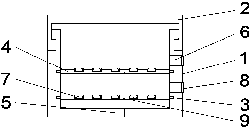
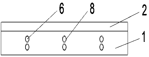
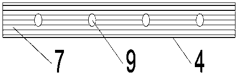
[0014] Such as Figure 1-3 As shown, a power wiring groove includes a main body 1 and a cover 2. The main body 1 is provided with a card slot 3, a fixing hole 5 and a tap hole 6. The card slot 3 is arranged on both sides of the main body 1, and the card slot 3 The threading plate 4 is threaded, and the threading plate 4 is provided with a threading groove 7 and a nail hole 9. The threading groove 7 is set on the horizontal surface of the threading plate 4, the nail hole 9 is set in the middle of the threading plate 4, and the fixing hole 5 is set In the middle of the bottom of the main body 1 , a branching hole 6 is arranged on the side of the main body 1 , a cap 8 is arranged on the branching hole 6 , and a cover 2 is arranged on the top of the main body 1 .

[00...


PUM


Abstract

The invention discloses an electric power wiring groove. The electric power wiring groove comprises a main body and a sealing cover, wherein clamping grooves, a fixing hole and shunting holes are formed in the main body; the clamping grooves are formed in the two sides in the main body; threading boards are arranged on the clamping grooves in a penetration manner; wire-passing grooves and nail-passing holes are formed in the threading boards; the wire-passing grooves are formed in the horizontal surfaces of the threading boards; the nail-passing holes are formed in middle of the threading boards; the fixing hole is formed in the middle of the bottom of the main body; the shunting holes are formed in the side surface of the main body; a hole cap is arranged on each shunting hole; and the sealing cover is arranged above the main body. The electric power wiring groove is simple in structure, and cables can be placed in the wiring groove attractively and tidily, so that circuit query becomes convenient.

Description

technical field [0001] The invention relates to an electric wiring groove. Background technique [0002] Wiring troughs, also known as wiring troughs, wiring troughs, and wiring troughs, are used to organize power cables, data cables and other wires in a standardized way, and fix electrical tools on the wall or ceiling. The cables placed inside the traditional wiring troughs are chaotic. Out of order, when the line fails, it is inconvenient to find, and the traditional wiring duct does not have a sub-interface. If you want to split, you need to destroy the trunking body. In order to solve the above problems, a new technical solution is provided. Contents of the invention [0003] The purpose of the present invention is to provide a power wiring trough to solve the problems raised in the background art above. [0004] In order to achieve the above object, the present invention adopts the following technical solutions: a power wiring groove, including a main body and a cove...

Claims


Application Information

Patent Timeline
Patent Type & Authority Patents(China)
IPC IPC(8): H02G3/04
CPCH02G3/0431
Inventor 蒋安美
Owner 广州寸金科技有限公司
Why Eureka
Try Eureka