Pedal controllable upper-and-lower type cushion turn-over device

A flipping device and cushion technology, which can be used in household appliances, sanitary equipment, applications, etc., can solve the problems of ineffective implementation, manual flipping of cushions, complex structure, etc., and achieve the effect of low manufacturing cost, strong concealment, and good effect

Inactive Publication Date: 2017-05-10
郑州勤睿恒电子科技有限公司
View PDF1 Cites 0 Cited by
  • Summary
  • Abstract
  • Description
  • Claims
  • Application Information

AI Technical Summary

Problems solved by technology

[0006] The purpose of the present invention is to solve the problem that the seat cushion of the traditional toilet must be turned over manually, and the existing pedal turning device has a complex structure, poor effect, and cannot be effectively implemented, and provides a simple structure, strong concealment, and high structural strength. , clean, hygienic, easy to use and reusable pedal controllable up and down seat cushion flip device

Method used


Image

  • Pedal controllable upper-and-lower type cushion turn-over device
  • Pedal controllable upper-and-lower type cushion turn-over device
  • Pedal controllable upper-and-lower type cushion turn-over device

Examples


Embodiment 1

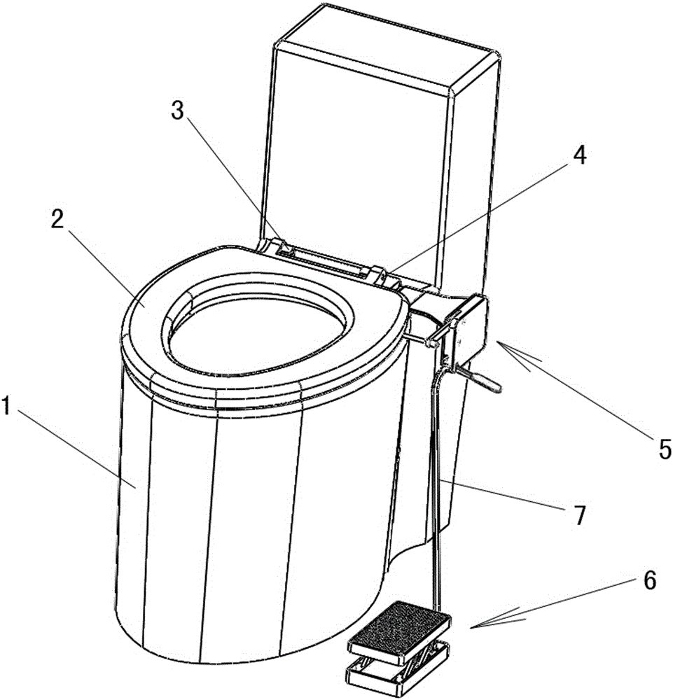
[0029] Embodiment 1: The first foot-operated controllable up-and-down seat cushion turnover device, see Figure 2 and Figure 3, includes a base, a swing rod, an inner shell and an outer shell, and a fixed shaft.

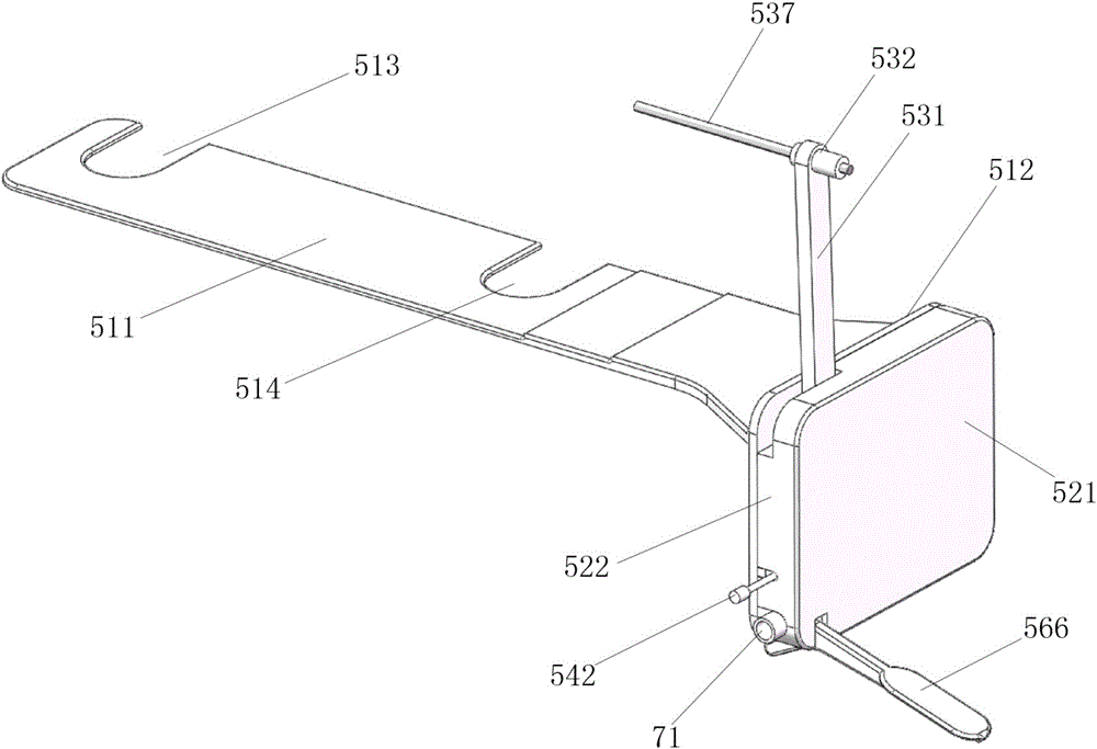
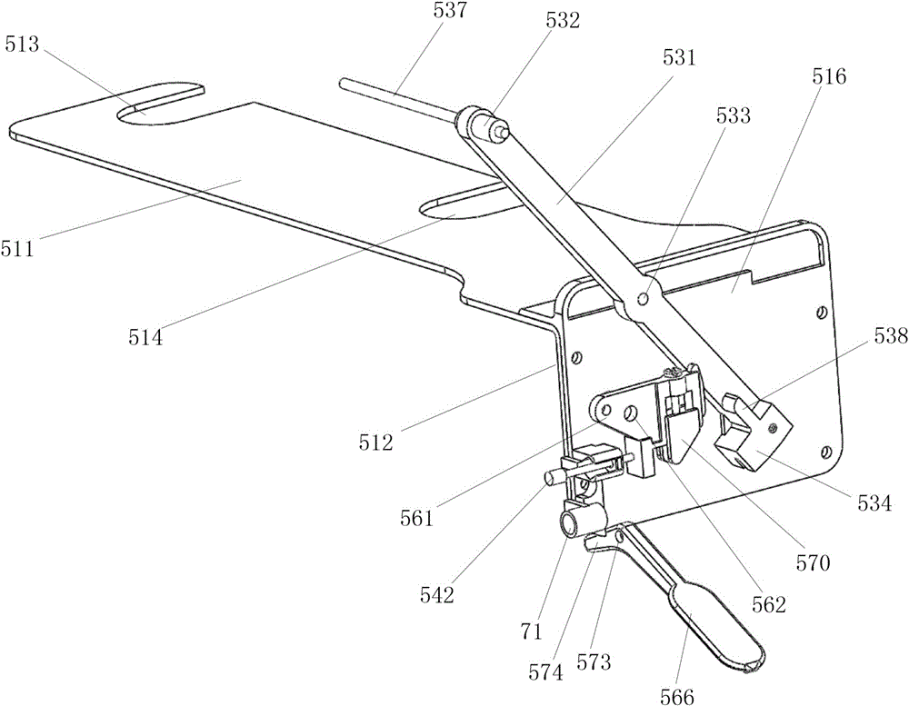
[0030] Referring to FIG. 1 and FIG. 5 , the base includes a base plate and side plates, and the base base plate 511 is fixed on the seat cushion rotating shaft seat 3 or between the seat cushion rotating shaft seat 3 and the toilet 1 . The base bottom plate 511 includes two jacks fixed on the outer side of the fixing bolt below the seat cushion shaft seat, and one jack is located at the end of the base bottom plate 511 and is a base end socket 513 . Another jack is located at the side of the base bottom plate 511 , the base side jack 514 .

[0031] An inner shell 516 and an outer shell are provided on the side of the base side plate 512 , the inner shell is attached to the side of the base side plate 512 , and the outer shell and the inner shell are interlocked. The ...

Embodiment 2

[0036] Embodiment 2: On the basis of Embodiment 1, the inner shell is deleted. That is, only a shell is provided on the side of the side plate 512 of the base, and the shell is wrapped around the outsides of each fixed axis and each moving axis. The first fixed shaft and the second fixed shaft are simultaneously connected between the shell and the side plate of the base.

Embodiment 3

[0037] Embodiment 3: On the basis of Embodiment 1, the inner shell and the outer shell are deleted. The fixed axis 1 and the fixed axis 2 are directly arranged on the outer surface of the side plate 512 of the base.


PUM


Abstract

The invention disclosed a pedal controllable upper-and-lower type cushion turn-over device. The cushion turn-over device comprises a base, a pedal device, an oscillating bar and a transmission device; the upper side of the forepart on the side surface of a base side plate is provided with a fixed shaft; the front end of the oscillating bar is provided with an oscillating bar front-end seat, the middle portion of the oscillating bar is provided with oscillating bar central-shaft hole, the back end of the oscillating bar is provided with an oscillating bar drawing head, and the oscillating bar central-shaft hole is hinged to the fixed shaft; the oscillating bar drawing head is connected with the pedal device in a transmission mode by the transmission device; the oscillating bar front-end seat is provided with a driving part that is capable of making contact with the bottom of a cushion; the cushion turn-over device is also provided with a flexible release mechanism. The base of the cushion turn-over device is fixed by a cushion rotational shaft seat of a water closet, so that most of the base is hidden and the base is good in concealment. A small shell can be fixed on the side plate of the base to keep the appearance clean and tidy. The whole cushion turn-over device does not touch the ground, and has the advantages of being simple in structure, reasonable in design, very easy to assemble and lower in manufacture cost.

Description

technical field [0001] The invention belongs to the technical field of toilet auxiliary tools, in particular to a device for directly driving a toilet seat cushion to turn over by a pedal connecting rod. Background technique [0002] Toilets exist in every family in the city, and more and more rural users have begun to use toilets. Restrooms in some high-end public places are also equipped with toilets. Ceramic or stainless steel toilets have the advantages of cleanliness, no peculiar smell, convenient use and good comfort, and will gradually replace traditional squatting toilets. [0003] Traditional toilets have always required users to bend down and turn them up and down with their hands, which brings a lot of inconvenience. Whether it is a family or a public place, it is unhygienic to lift the cushion by hand, especially when the finger is lifted, it must touch the bottom of the cushion, and the bottom of the cushion is in direct contact with the upper edge of the toil...

Claims


Application Information

Patent Timeline
IPC IPC(8): A47K13/10A47K13/24A47K13/28
CPCA47K13/10A47K13/24A47K13/28
Inventor 孙明英
Owner 郑州勤睿恒电子科技有限公司
Why Eureka
Try Eureka