Convenient-to-replace immersion heater device with high safety

A safety and heating part technology, applied in the direction of electric heating devices, immersion heating devices, heating elements, etc., can solve the problems of increased difficulty of replacement, increased use cost, damage, etc., to reduce operating steps, improve replacement efficiency, The effect of increasing stability

Active Publication Date: 2017-05-31
甘肃太阳雨能源集团有限公司
View PDF3 Cites 9 Cited by
  • Summary
  • Abstract
  • Description
  • Claims
  • Application Information

AI Technical Summary

Problems solved by technology

[0002] As a commonly used water heating appliance, fast heating is recognized by people for its many advantages such as direct heating, convenient operation, quick introduction, energy saving and power saving, and it is used more and more widely. Damage will inevitably occur under long-term use. The traditional medium heats faster and is more integrated. If the heating tube is damaged and cannot be used, it needs to be purchased again, which increases the cost of use. There are also many existing technologies that can replace the heating tube. The heating device of the tube is fast, but its power supply part is designed to increase safety due to waterproof and leakage, and the conductive contact part is set relatively inside, which makes the heating tube prone to poor contact and cannot be heated normally after replacement, making replacement difficult. Increased, unable to meet existing needs, needs to be improved

Method used


Image

  • Convenient-to-replace immersion heater device with high safety
  • Convenient-to-replace immersion heater device with high safety
  • Convenient-to-replace immersion heater device with high safety

Examples


Embodiment Construction

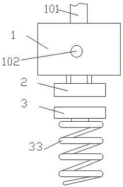
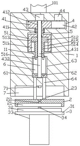
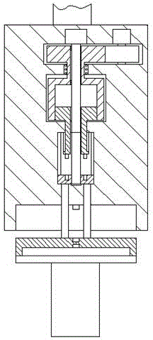
[0020] Such as Figure 1-Figure 4 As shown, an easy-to-replace and high-safety quick-heating device of the present invention includes a power supply end 1 and a heating part 3 arranged below the bottom of the power supply end 1 , and the inside of the power supply end 1 is from top to bottom. And the first cavity 4, the second cavity 5 and the third cavity 6 are provided successively, the bottom end surface of the power supply end 1 is provided with a connecting groove 7, and the first cavity 4 is provided with a first Toothed wheel 41, the right side of the first toothed wheel 41 is meshed with a second toothed wheel 42, the top of the second toothed wheel 42 is connected with the first driving machine 44, the first toothed wheel 41 The bottom is provided with a drive shaft 411 that penetrates through the wall of the power supply end 1 and extends into the second cavity 5, and the second cavity 5 is provided with a sleeve that is fixedly connected to the drive shaft 411 at th...


PUM


Abstract

The invention discloses a convenient-to-replace immersion heater device with high safety. The immersion heater device comprises a power supply end part and a heating part arranged at the lower side of the bottom of the power supply end part, wherein a first cavity, a second cavity and a third cavity are sequentially arranged inside the power supply end part from top to bottom; a connecting groove is formed in the bottom end surface of the power supply end part; a first toothed wheel is arranged in the first cavity; the right side of the first toothed wheel is connected with a second toothed wheel in an engaged way; the top of the second toothed wheel is connected with a first driving machine; a driving shaft which penetrates through the wall body of the power supply end part and extends into the second cavity is arranged at the bottom of the first toothed wheel; a sleeve with the top fixedly connected with the driving shaft is arranged in the second cavity; an inner spiral thread cavity is arranged in the sleeve; inner spiral threads of the inner spiral thread cavity are connected with an ascending and descending block in a matched way; a first through connecting hole penetrated in the vertical direction is formed in the ascending and descending block; a second through connecting hole penetrated in the vertical direction is formed in the first toothed wheel and the driving shaft; a transfer shaft in vertical extension arrangement is arranged in the second through connecting hole; the top end of the transfer shaft is connected with a second driving machine; the bottom extension section of the transfer shaft passes through the second through connecting hole and the inner spiral thread cavity and extends into the third cavity.

Description

technical field [0001] The invention relates to the technical field of household electrical appliances, in particular to a fast heating device which is easy to replace and has high safety. Background technique [0002] As a commonly used water heating appliance, fast heating is recognized by people for its many advantages such as direct heating, convenient operation, quick introduction, energy saving and power saving, and it is used more and more widely. Damage will inevitably occur under long-term use. The traditional medium heats faster and is more integrated. If the heating tube is damaged and cannot be used, it needs to be purchased again, which increases the cost of use. There are also many existing technologies that can replace the heating tube. The heating device of the tube is fast, but its power supply part is designed to increase safety due to waterproof and leakage, and the conductive contact part is set relatively inside, which makes the heating tube prone to poo...

Claims


Application Information

Patent Timeline
Patent Type & Authority Applications(China)
IPC IPC(8): H05B3/80H05B3/02H05B3/08
CPCH05B3/02H05B3/08H05B3/80H05B2203/003H05B2203/021
Inventor 张灵杰
Owner 甘肃太阳雨能源集团有限公司
Why Eureka
Try Eureka