Fixing device and fixing assembly thereof

A technology for fixing devices and fixing components, which is applied in the direction of connecting components, casing/cabinet/drawer parts, thin plate connection, etc., which can solve the problems of unfavorable and fast assembly, time-consuming and inconvenient operation, and cumbersome assembly process, etc.

Active Publication Date: 2018-03-27
HANWIT PRECISION IND LTD
View PDF4 Cites 5 Cited by
  • Summary
  • Abstract
  • Description
  • Claims
  • Application Information

AI Technical Summary

Problems solved by technology

[0003] Furthermore, electronic devices such as motherboards, power supplies, hard disks, and fans are usually installed inside the server cases of general computers or industrial computers. Many copper pillars need to be set on the bottom plate of the chassis, and the main board is placed flat on the plurality of copper pillars, and then the screws are used to pass through the through holes on the main board and then locked into the copper pillars to lock and fix them into one body. However, with the growth of the manufacturer's chassis shipments, the number of copper pillars on the bottom plate will also increase multiples. This method of locking and fixing the main board and the bottom plate by using screws locked in the copper pillars not only It is easy to be limited by the limited space inside the casing, which makes the user spend more time and manpower on the operation, and is not conducive to rapid assembly, resulting in the overall assembly process becoming more cumbersome and time-consuming and inconvenient to operate. It needs to be redesigned by those engaged in this industry to effectively solve

Method used


Image

  • Fixing device and fixing assembly thereof
  • Fixing device and fixing assembly thereof
  • Fixing device and fixing assembly thereof

Examples


Embodiment Construction

[0038] In order to achieve the above-mentioned purpose and effect, the technical means adopted in the present invention, its structure, and the method of implementation, etc., are hereby described in detail with respect to the preferred embodiments of the present invention. Its features and functions are as follows, so that it can be fully understood.

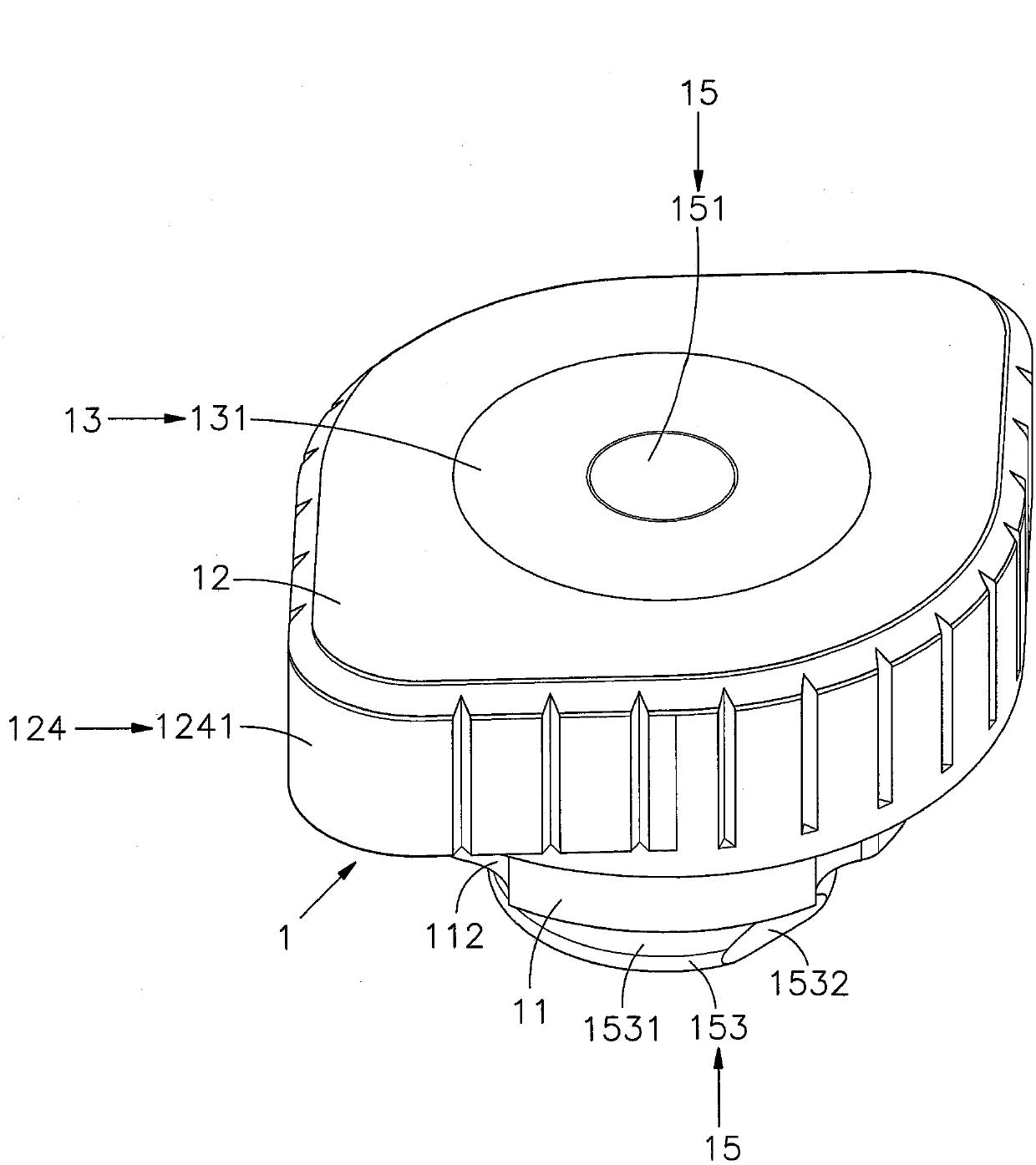
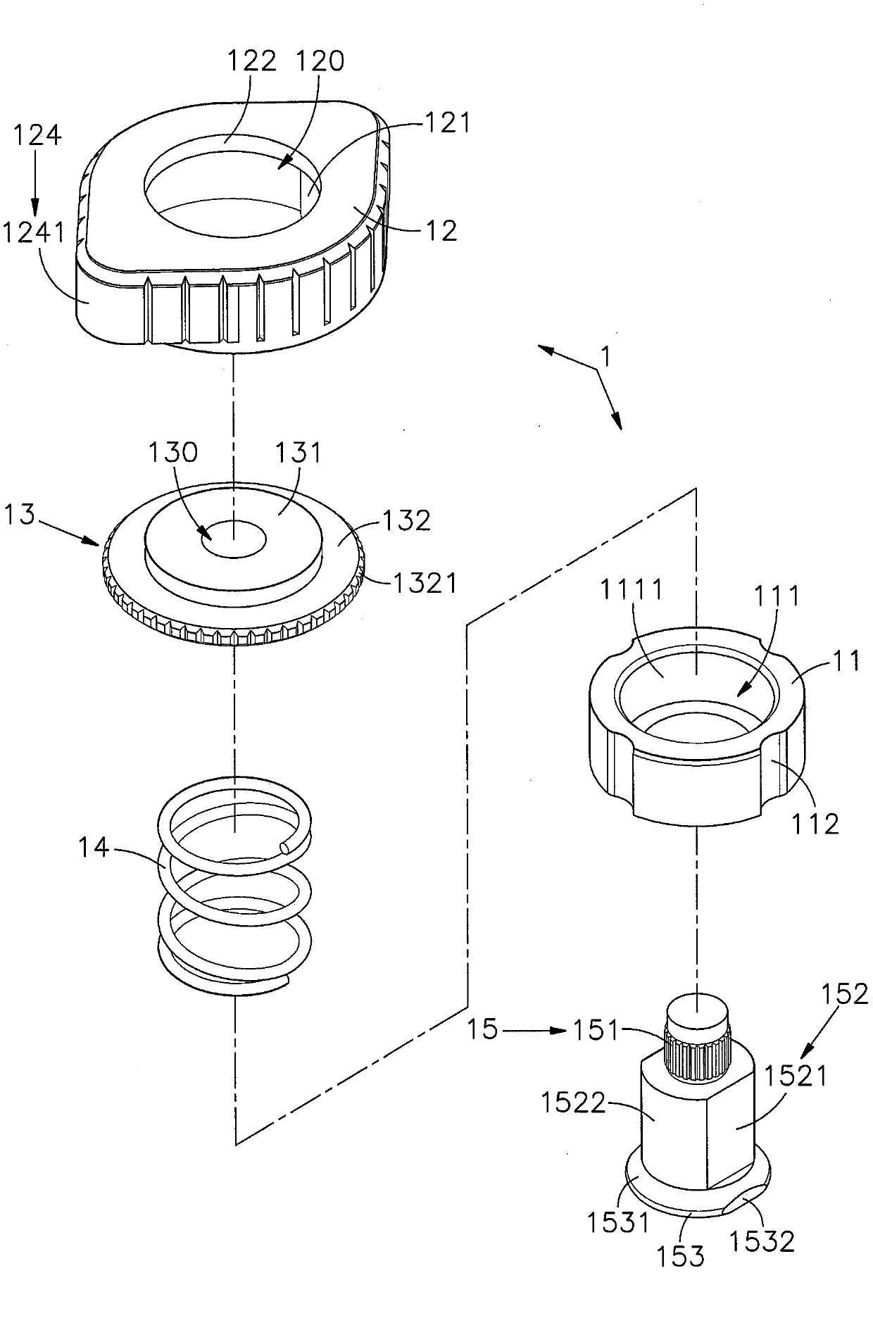
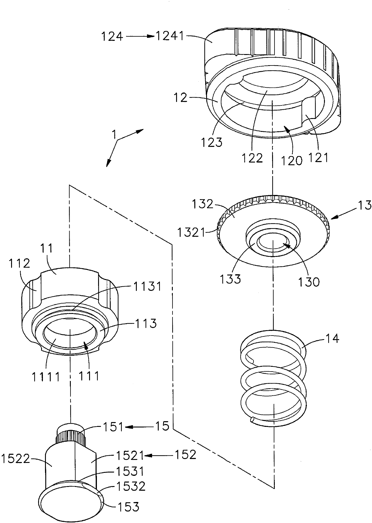
[0039] see figure 1 , figure 2 , image 3 , Figure 4Shown are the three-dimensional appearance diagram of the fixed assembly of the preferred embodiment of the present invention, the three-dimensional exploded view of the fixed assembly, another three-dimensional exploded view of the fixed assembly, and the three-dimensional appearance diagram before assembly. It can be clearly seen from the figure that the present invention The fixing device includes a fixing component 1, a first plate 2 and a second plate 3, wherein:

[0040] The fixing assembly 1 includes a sleeve 11, an outer sleeve 12, a head 13, an elastic element 14...


PUM


Abstract

The invention provides a fixing device and a fixing assembly thereof. A penetrating hole is formed in a sleeve. A plurality of grooves are formed in the surface of the sleeve in an annular mode. The sleeve is arranged in an accommodating space of an outer casing. The inner wall surface of the accommodating space is provided with at least one convex rib which can slide in the multiple grooves. Theaccommodating space is internally provided with a head part with an embedded hole. An elastic element is arranged between the head part and the sleeve. The lower portion of the sleeve is provided witha fixed part fixed to the head part. The fixed part is provided with a riveting part embedded and fixed in the embedded hole. A rod body is extended from the lower portion of the riveting part. The surface of the rod body is provided with two opposite longitudinal sections and two opposite arc surfaces. The bottom of the rod body is provided with a guiding inclined surface. When the sleeve is fixed on a first plate, abutting-against surfaces on the two sides of a section surface of a second plate can be used to push for abutting against the guiding inclined surface, so that the rod body penetrates through the section groove to enter a clamping fixing groove; the elastic element is reset so that a blocking stopping part is located in the clamping fixing groove, and then the outer casing isrotated so that exact positioning is achieved; and the outer casing is rotated and the outer casing or the head part is pressed again, the second plate can be removed outwards, so that the rapid disassembly and assembly effects are achieved.

Description

technical field [0001] The invention relates to a fixing device, in particular to a fixing component that uses the guide inclined surface of the stop part to push the two sides of the cut groove of the second plate, so that the rod body passes through the cut groove and enters the clamping groove, and the elastic element resets and then rotates the outer casing to achieve The stop part is located in the clamping groove to form a positioning, and then the outer sleeve is rotated and the outer sleeve or the head is pushed to detach the second plate, so as to achieve the effect of accurate positioning and convenient disassembly and assembly. Background technique [0002] Press, with the continuous advancement of electronic technology, many products will use screws or pins for positioning, such as drawers, keyboard frames, board sets and other products with movable and telescopic structures, and use screws or pins to make slide rails, The chute forms a positioning when it moves ...

Claims


Application Information

Patent Timeline
Patent Type & Authority Applications(China)
IPC IPC(8): F16B5/04H05K5/02
CPCF16B5/04H05K5/02
Inventor 吴明德陈智远
Owner HANWIT PRECISION IND LTD
Why Eureka
Try Eureka