Drive rivet

A technology of rivets and mandrels, applied in the field of rivets, can solve the problems of insufficient force of the cap and the strength of riveting to be improved, and achieve the effect of strengthening the strength of riveting

Inactive Publication Date: 2018-06-01
陈业国
View PDF0 Cites 0 Cited by
  • Summary
  • Abstract
  • Description
  • Claims
  • Application Information

AI Technical Summary

Problems solved by technology

It also has the disadvantage that the force on the cap is not strong enough after the mandrel is hit, so the riveting strength needs to be improved

Method used


Image

  • Drive rivet
  • Drive rivet
  • Drive rivet

Examples


Embodiment Construction

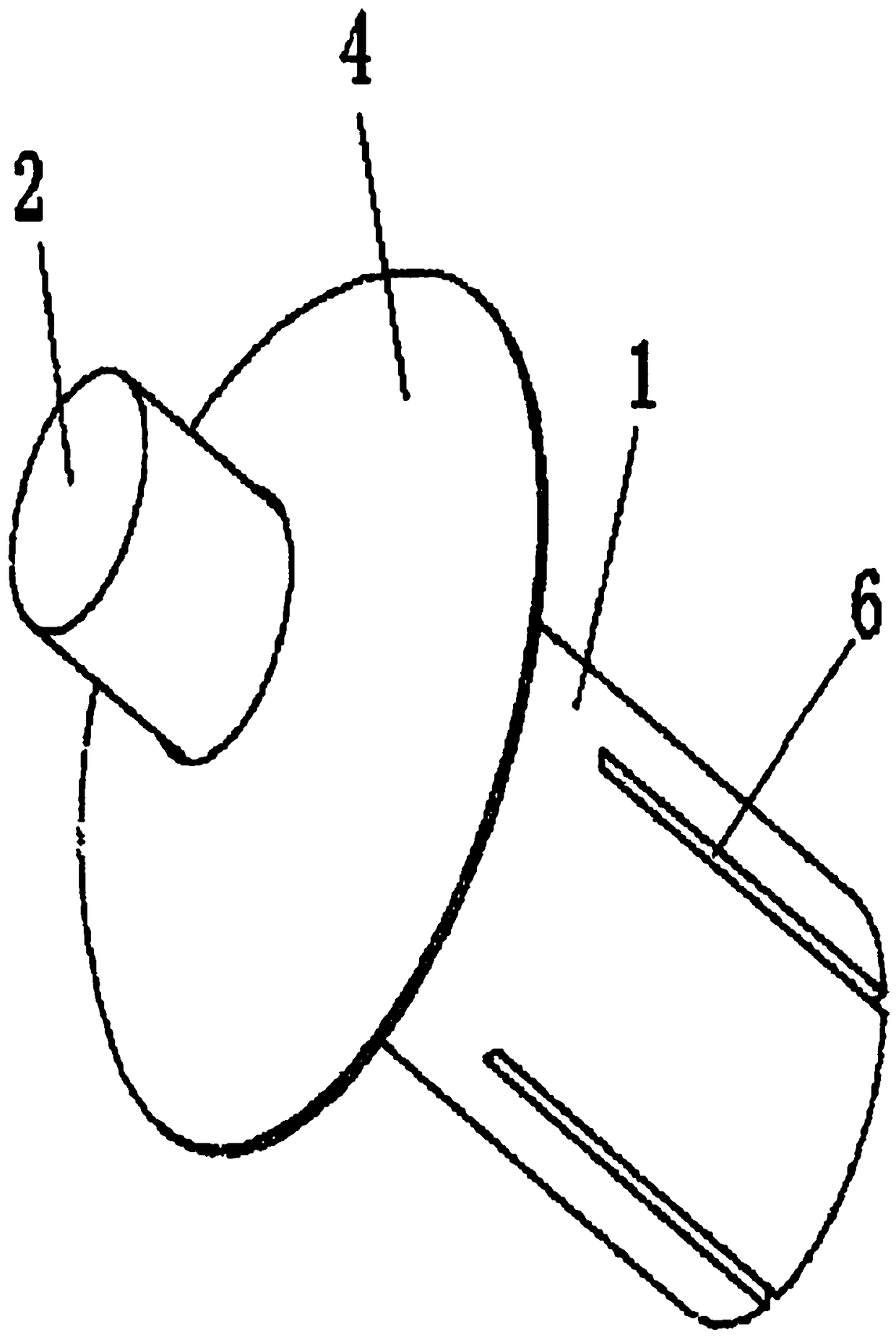
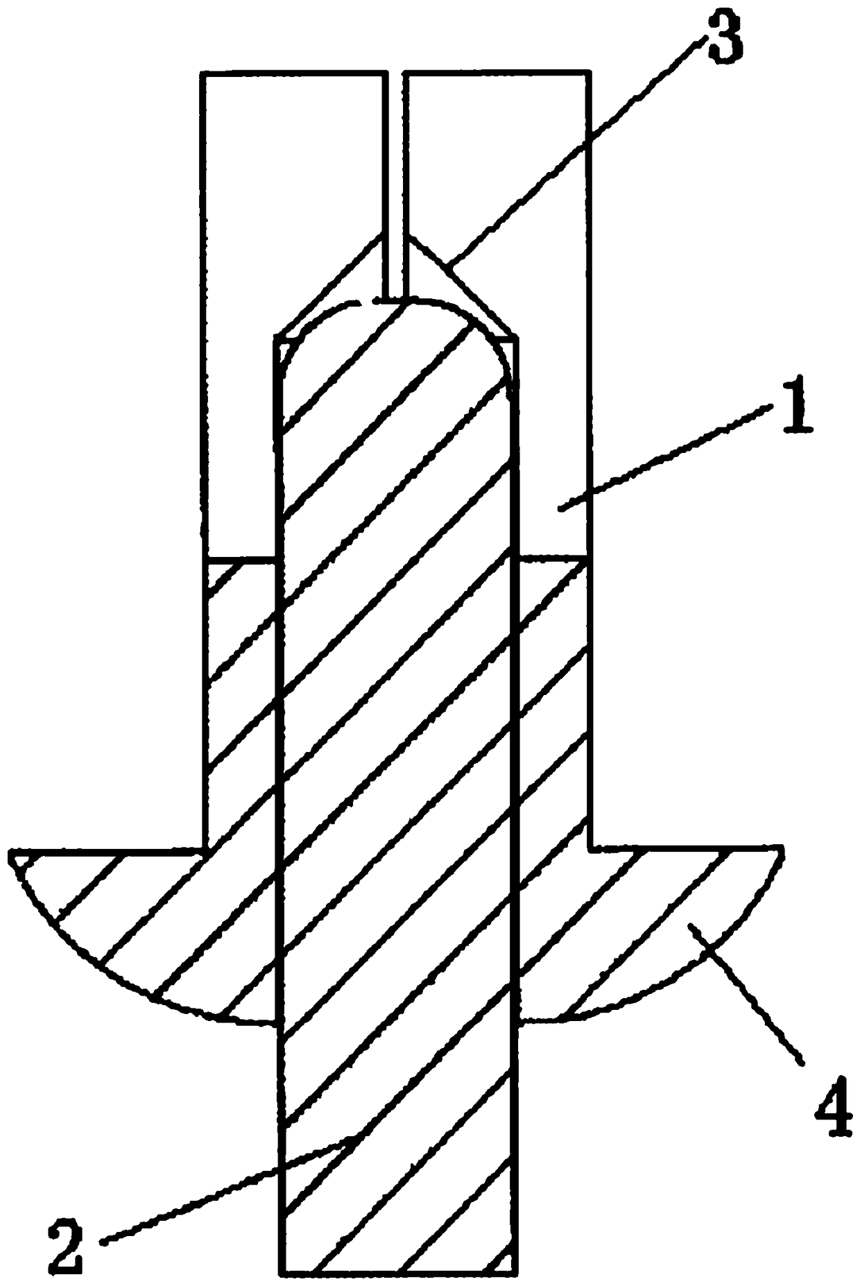
[0013] refer to figure 1 , figure 2 , image 3 , a core rivet, comprising a cap 1, the cap 1 is provided with a crack, the cap 1 has an insertion cavity, a mandrel 2 is inserted in the cavity, and the insertion cavity The bottom surface 3 is conical with the tip of the cone facing outwards. In this embodiment, the rear end of the cap 1 is provided with a flange 4 .

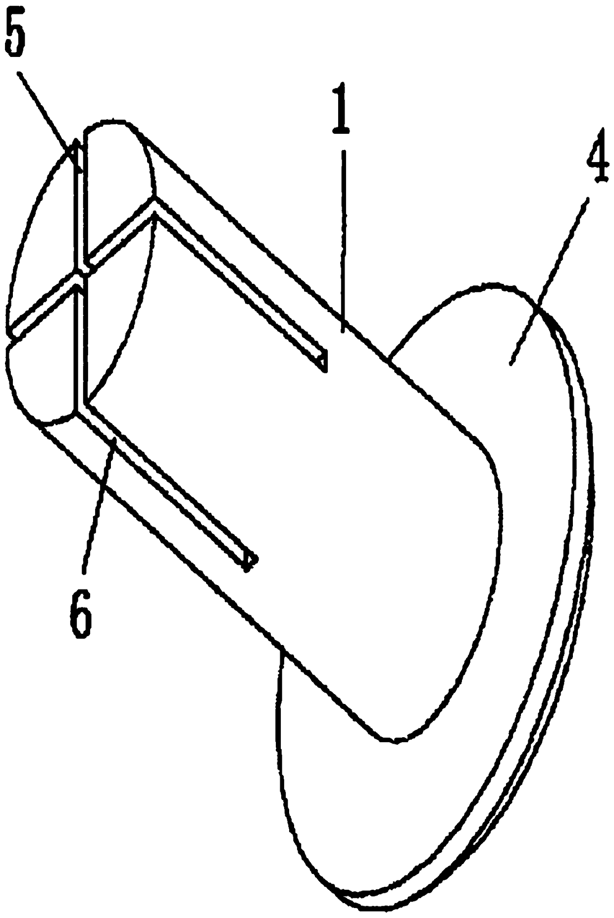
[0014] In this embodiment, there are four cracks, and the four cracks are evenly distributed on the cap; each crack includes a radial crack 5 and an axial crack 6, and the radial crack 5 starts from The center of the front end face of the cap extends outwards, and the head of the axial crack 6 connects with the tail of the radial crack 5 and extends backward on the side wall of the cap 1 .

[0015] The usage method of the present invention is the same as the usage method of the existing core rivet, and will not be repeated here.

[0016] Since the bottom surface 3 of the insertion cavity is in the shape of a...


PUM


Abstract

A drive rivet comprises a pipe cap; cracks are formed in the pipe cap; the pipe cap comprises an inserting cavity; a rivet core is inserted in the inserting cavity; and the bottom surface of the inserting cavity is in the conical shape with the conical tip facing outwards. The bottom surface of the inserting cavity is in the conical shape with the conical tip facing outwards, so that when the rivet core is struck, the acting force of the rivet core on the pipe cap is very large, the pipe cap can be blasted enough, and the riveting strength can be enhanced.

Description

technical field [0001] The invention relates to a core hammer rivet. Background technique [0002] The general structure of the core-hitting rivet is as follows: it includes a cap, the cap is provided with cracks, the cap has an insertion cavity, and a nail core is inserted in the insertion cavity, and the nail core is hit during use. , so that the pipe cap is torn apart along the crack, so as to achieve the purpose of riveting. It also has the disadvantage that the force of the mandrel on the cap is not strong enough after being hit, so the riveting strength needs to be improved. Contents of the invention [0003] In order to overcome the above-mentioned shortcomings of the existing core rivets, the present invention provides a core rivet with better riveting strength. [0004] The technical solution of the present invention to solve the technical problem is: a core striking rivet, including a cap, the cap is provided with cracks, the cap has an insertion cavity, and a ...

Claims


Application Information

Patent Timeline
Patent Type & Authority Applications(China)
IPC IPC(8): F16B19/10
CPCF16B19/10F16B2019/1009F16B19/1081
Inventor 陈业国
Owner 陈业国
Why Eureka
Try Eureka