Mobility management method between wireless access networks, core network equipment and base station

A wireless access network and management method technology, applied in the field of core network equipment and base stations, can solve the problems that the terminal cannot continue to maintain the inactive state, cannot work normally, and the terminal behavior is uncertain, etc.

Active Publication Date: 2019-12-20
DATANG MOBILE COMM EQUIP CO LTD
View PDF3 Cites 0 Cited by
  • Summary
  • Abstract
  • Description
  • Claims
  • Application Information

AI Technical Summary

Problems solved by technology

[0013] From the above analysis, it can be seen that the existing technology only defines the inactive state of the NR system. When the UE in the inactive state moves from the NR system to other communication systems (such as the LTE / eLTE system), since other communication systems do not have an inactive state, The terminal will not be able to remain inactive. At this time, the behavior of the terminal is uncertain and cannot work normally.

Method used


Image

  • Mobility management method between wireless access networks, core network equipment and base station
  • Mobility management method between wireless access networks, core network equipment and base station
  • Mobility management method between wireless access networks, core network equipment and base station

Examples


Embodiment 1

[0144] This embodiment is aimed at figure 2 with image 3 The application scenario shown illustrates the behavior of the terminal side.

[0145] The embodiment of the present invention provides an inter-RAN mobility management method, which is applied between RANs based on different RATs. Specifically, the foregoing RAN includes a first RAN and a second RAN, where the first RAN is a new air interface NR The RAN of the system, the second RAN may be the RAN of the 3G system or the 4G system, or the RAN of the LTE system or the eLTE system. The subsequent embodiments of this document will mainly take the LTE system and the eLTE system as examples. It should be pointed out that the second RAN in the embodiment of the present invention is not limited to the RAN of the LTE system and the eLTE system.

[0146] Please refer to Figure 4 When the mobility management method provided in the embodiment of the present invention is applied to the terminal side, it includes the following steps:...

Embodiment 2

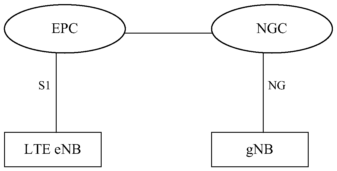
[0170] This embodiment is aimed at figure 2 The application scenario shown illustrates the core network behavior on the NR side.

[0171] Please refer to Figure 5 In the method for mobility management between radio access network RANs provided in the embodiment of the present invention, the RAN here includes a first RAN and a second RAN. Here, the first RAN is the RAN of the NR system, and the second RAN is the eLTE RAN. The mobility management method is applied to the first core network side of the NR system and includes the following steps:

[0172] Step 51: The first core network of the NR system receives the paging failure message sent when the first base station in the first RAN cannot page the first terminal in the inactive state in the RAN-level location area RNA, so The first base station is a base station that stores user context information of the first terminal in the NR system.

[0173] Step 52: The first core network initiates paging to the first terminal in a core n...

Embodiment 3

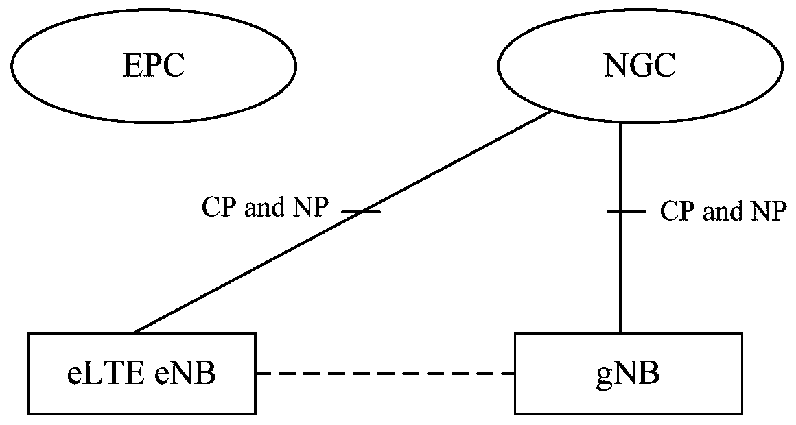
[0185] This embodiment is aimed at image 3 The application scenario shown illustrates the core network behavior on the NR side.

[0186] Please refer to Image 6 In the method for mobility management between radio access network RANs provided in the embodiment of the present invention, the RAN here includes a first RAN and a second RAN. Here, the first RAN is the RAN of the NR system, and the second RAN is the RAN of the LTE. The mobility management method is applied to the first core network side of the NR system and includes the following steps:

[0187] Step 61: The first core network of the NR system receives a prompt message sent by the terminal in the second RAN during the RRC connection establishment process, and the prompt information is used to prompt the first base station in the first RAN. The first base station is a base station that stores user context information of the terminal in the NR system.

[0188] Here, the RRC connection establishment process may be triggere...


PUM


Abstract

The present disclosure provides an inter-radio access network mobility management method, a core network device, and a base station. When an inter-system movement occurs on a terminal in an inactive state, user context information of the terminal in the inactive state in NR system is still retained; and the user context information is deleted until certain conditions are satisfied. The disclosure achieves inter-RAY mobility management of a terminal in an inactive state and solves an inter-system mobility problem, so that the terminal can operate normally.

Description

Technical field [0001] The present invention relates to the field of mobile communication technology, in particular to a mobility management method between wireless access networks, core network equipment and base stations. Background technique [0002] With the development of wireless communication systems, terminal types and service types are diversified, and the terminals save power, save network resources and meet the needs of various service types. In order to ensure both terminal power saving and fast data transmission, a new mobility state is introduced in the New Radio Access Technology (New RAT) of the 5G New Air Interface (NR) system: RRC_INACTIVE (also called inactive state in this article) Or inactive state). [0003] In the inactive state, the terminal maintains the core network connection, but does not perform normal operations in the air interface connection state (such as handover, uplink timing update, radio link monitoring, etc.), and does not allocate terminal i...

Claims


Application Information

Patent Timeline
Patent Type & Authority Patents(China)
IPC IPC(8): H04W36/14H04W76/27
CPCH04W36/14H04W88/06H04W4/00
Inventor 梁靖
Owner DATANG MOBILE COMM EQUIP CO LTD
Why Eureka
Try Eureka