Al technical title is built by PatSnap Al team. It summarizes the technical point description of the patent document.
A technology for display screens and computers, which is applied in the direction of supporting machines, mechanical equipment, machine tables/brackets, etc. It can solve the problems of difficulty in disassembly and assembly, space occupied by the display screen, and great practicability, so as to save carrying space, save space, Practical effect
Inactive Publication Date: 2018-11-27
代欣
View PDF3 Cites 3 Cited by
Summary
Abstract
Description
Claims
Application Information
AI Technical Summary
This helps you quickly interpret patents by identifying the three key elements:
Problems solved by technology
Method used
Benefits of technology
Problems solved by technology
[0002] With the continuous progress of the society, the structure of the computer display screen is various. When meeting people's daily use, the computer display screen can change the upward angle of the display screen in order to meet people's line of sight. The display screen takes up a lot of space, and the base area of the display screen is large and difficult to disassemble. Commonly used display screens cannot be raised or lowered according to the height of the human body, and the height of the display screen cannot be turned left and right. The limitations are large and the practicability is not perfect.
Method used
Image
Click on the blue label to locate the original text in one second.
Reading with bidirectional positioning of images and text.
Examples
Embodiment Construction
[0013] The present invention will be further elaborated below with reference to the accompanying drawings and specific embodiments.
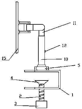
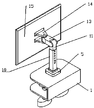
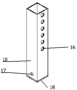
[0014] like Figure 1-4 As shown, a computer display screen structure includes a fixture 1, a screw 2, a knob 3, a top pad 4, a connecting seat 5, a connecting groove 6, a magnetic block 7, a top pin 8, a spring 9, a support column 10, a telescopic column 11. Spring pin 12, connecting piece 13, display screen connection seat 14, display screen 15, the fixture 1 is a U-shaped structure, the bottom of the fixture is threadedly connected with two screws 2, and the bottom of the screw 2 is provided with a knob 3, The top of the screw 2 is provided with a top pad 4, the top surface of the clamp 1 is fixed with a connecting seat 5, the center of the connecting seat 5 is provided with a connecting groove 6, and the bottom of the connecting groove 6 is fixed with a magnetic block 7. There are ejector pins 8 on both sides of the connection slot 6, the e...
PUM
Abstract
A compute display screen structure including fixtures, Screw, knob, top cushion, Connecting groove, magnetic suction block, ejector pin, support column, telescopic column, spring pin, Display Screen Connector, a display screen, wherein the fixture is of a U-shaped structure, A low part of that jig is threadably connected with the two screw, A knob is arranged at the bottom of the screw rod, A toppad is arranged at the top of the screw rod, A connector is fixed on the top surface of the fixture, At that cent of the connecting seat is provide with a connecting groove, A magnetic suction block is fix at that bottom of the connecting groove, top pin are arranged on both sides of the connecting groove, springs are connected at the ends of the top pins, semicircular structures of the front endsof the top pins are arranged in the connecting groove, the supporting columns are slidably connected with the connecting groove, the inner walls of the supporting columns are slidably connected withthe telescopic columns, and the lower parts of the telescopic columns are provided with spring pins. The invention is convenient to place on the desktop of various thicknesses, and can adjust the angle of the display screen up, down, left and right.
Description
technical field [0001] The invention relates to a display screen structure, in particular to a computer display screen structure. Background technique [0002] With the continuous progress of society, the structure of computer display screen is various. When it meets people's daily use, the computer display screen can change the upward angle of the display screen to meet people's sight, while in daily leisure or office, facing a narrow desktop The display screen occupies a lot of space, and the display base area is large, and it is difficult to disassemble and assemble. The commonly used display screen cannot be raised or lowered according to the height of the human body, and the height of the display screen cannot be turned left or right, which is limited and not perfect. SUMMARY OF THE INVENTION [0003] The purpose of the present invention is to provide a computer display screen structure to solve the above technical problems. [0004] For achieving the above object, t...
Claims
Application Information
Patent Timeline
Application Date:The date an application was filed.
Publication Date:The date a patent or application was officially published.
First Publication Date:The earliest publication date of a patent with the same application number.
Issue Date:Publication date of the patent grant document.
PCT Entry Date:The Entry date of PCT National Phase.
Estimated Expiry Date:The statutory expiry date of a patent right according to the Patent Law, and it is the longest term of protection that the patent right can achieve without the termination of the patent right due to other reasons(Term extension factor has been taken into account ).
Invalid Date:Actual expiry date is based on effective date or publication date of legal transaction data of invalid patent.