
A car door stopper
A technology for automobile doors and limiters, which is applied in the direction of building fastening devices, wing fastening devices, buildings, etc., can solve the problem of reducing the limiting torque, weakening the elastic force of springs or rubber, affecting the overall performance of the vehicle, etc. problem, to achieve the effect of increasing the amount of pre-compression and reducing the degree of reduction
- Summary
- Abstract
- Description
- Claims
- Application Information
AI Technical Summary
Problems solved by technology
Method used
Image

Examples
Embodiment Construction
[0033] The specific implementation manners of the present invention will be further described in detail below in conjunction with the accompanying drawings and embodiments. The following examples or drawings are used to illustrate the present invention, but not to limit the scope of the present invention.
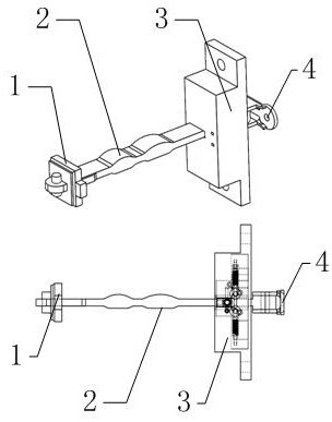
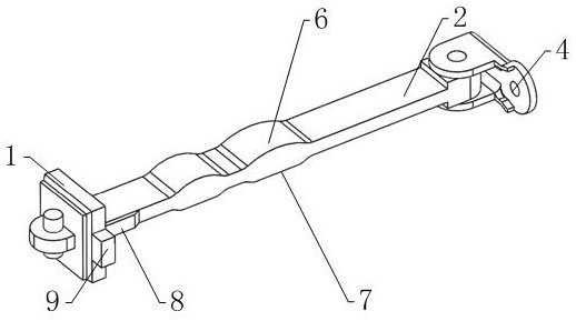
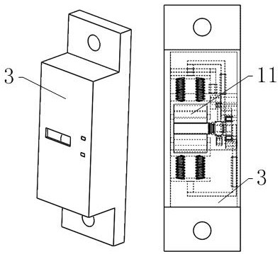
[0034] like figure 1 As shown, it includes a mounting bracket 4 fixed on the car body, a limit box 3 fixed on the door, a rubber buffer block 1 providing a buffer force, a limit arm 2, and a clamping mechanism 11, wherein as figure 2 As shown, the upper and lower ends of the limit arm 2 are respectively provided with two limit protrusions 6 distributed along the length direction of the limit arm 2, and one end of the limit arm 2 is mounted on the mounting bracket 4 in a hinged manner, and the rubber The buffer block 1 is installed on the other end of the limit arm 2, and is limited by the pin installed on the limit arm 2; the limit arm 2 passes through the limit box 3 and...
PUM
 Abstract
Description
Claims
Application Information