Electric seesaw swing

A seesaw swing and electric technology, which is applied in the fields of entertainment equipment and sports, can solve the problems that the swing does not have any, cannot run automatically, and the movement form is monotonous, and achieves the effects of simple and reliable control mode, simple structure and various use modes.

Pending Publication Date: 2020-11-06
HANGZHOU HANDOU TECH CO LTD
View PDF1 Cites 0 Cited by
  • Summary
  • Abstract
  • Description
  • Claims
  • Application Information

AI Technical Summary

Problems solved by technology

[0002] Swing has a long history. It mainly uses gravity to swing back and forth. It has the characteristics of simple structure and convenient use, but its movement form is monotonous.
Although the structure of the swing is various at present, the form of motion is still a simple swing back and forth, the motion is monotonous, the playability is poor, and it cannot run automatically. It is CN111134486A, which includes a swing frame, the bottom ends of both sides of the swing frame are respectively fixedly connected with fixed plates, and the upper surface of the fixed plate is rotated and installed with evenly distributed fixed bolts, and the fixed bolts penetrate the lower surface of the fixed plate. The top of the swing frame is fixedly equipped with two symmetrically distributed rotating shaft brackets, and a rotating shaft is fixedly installed between the two rotating shaft brackets, and the two ends of the rotating shaft run through the two rotating shaft brackets respectively. The essence of the invention It is an inevitable trend of development to research and produce a swing with multiple styles of use, and the market prospect is great.

Method used


Image

  • Electric seesaw swing
  • Electric seesaw swing
  • Electric seesaw swing

Examples


Embodiment Construction

[0042] The present invention will be further described below in conjunction with the accompanying drawings, but the present invention is not limited to the following examples.

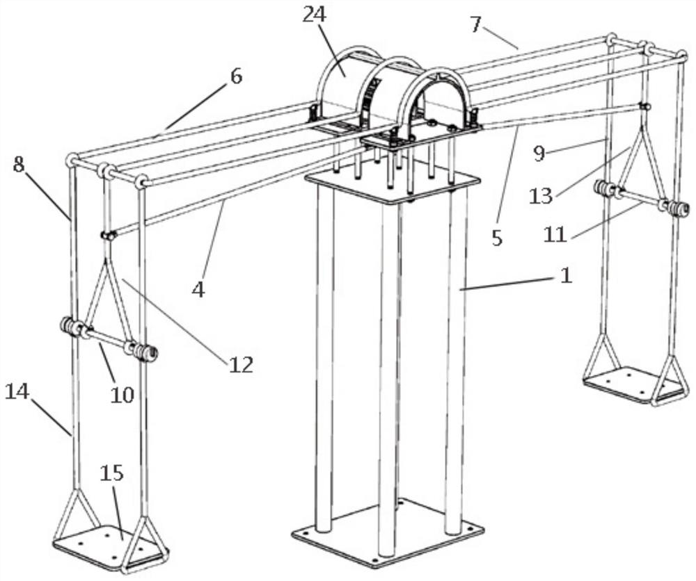
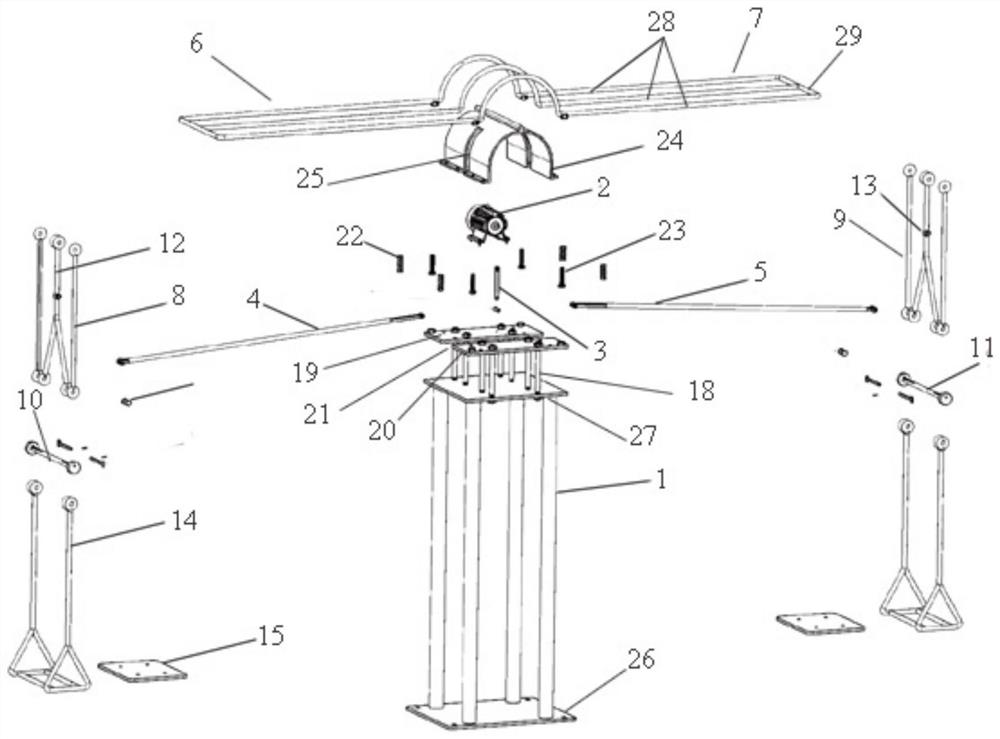
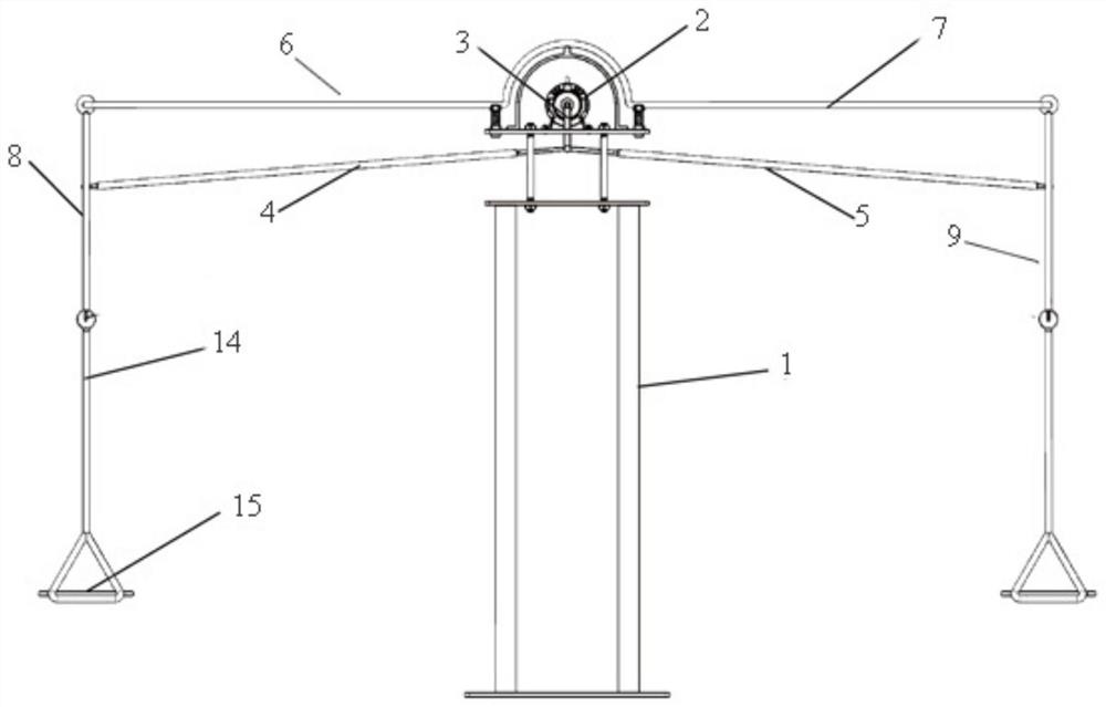
[0043] Such as Figure 1-24Shown is a specific embodiment of an electric seesaw swing. This embodiment is an electric seesaw swing, including a column 1, a motor 2 is installed on the top of the column 1, a rocker 3 is connected to the rotating shaft of the motor 2, and a left swing bar 4, Right pendulum 5, one end of left pendulum 4 and right pendulum 5 are all hinged with the free end of rocker 3, and the left and right ends at the top of column 1 are respectively connected with left top frame 6 and right top frame 7 and form a T-shaped structure, Two No. 1 upper rack rods 8 are hinged at the end of the left top frame 6, two No. 2 upper rack rods 9 are hinged at the end of the right upper rack 7, and the bottom ends of the No. 1 upper rack rod 8 and the second No. 2 upper rack rods 9 are respectively...


PUM


Abstract

The invention discloses an electric seesaw swing. A motor is arranged on the tops of stand columns, a rocker is connected with the motor, and the rocker is hinged with a left swing rod and a right swing rod; a left top frame and a right top frame are connected to the tops of the stand columns; the left top frame is hinged to two first upper frame rods; the right top frame is hinged with two secondupper frame rods; a first hanging frame rod is arranged between the first upper frame rods in a penetrating mode, a second hanging frame rod is arranged between the second upper frame rods in a penetrating mode. A first inner frame rod and a second inner frame rod are respectively hinged on the first hanging frame rod and the second hanging frame rod respectively; the upper ends of the first inner frame rod and the second inner frame rod are hinged to the left top frame and the right top frame respectively. The left swing rod and the right swing rod are connected to the first inner frame rodand the second inner frame rod respectively. Lower frame rods are hinged to the front ends and the rear ends of the first hanging frame rod and the second hanging frame rod; the lower frame rods are connected with seats, locking mechanisms are inserted among the first upper frame rods, the first inner frame rod and the lower frame rods which are hinged to the first hanging frame rod and among thesecond upper frame rods, the second inner frame rod and the lower frame rods which are hinged to the second hanging frame rod respectively. The electric seesaw swing has multiple using modes, and is easy to operate, pure in mechanical structure and easy to produce in batches.

Description

technical field [0001] The invention relates to a swing, and more specifically relates to an electric seesaw swing, which belongs to the field of sports and entertainment equipment. Background technique [0002] Swing has a long history. It mainly uses gravity to swing back and forth. It has a simple structure and is easy to use, but its motion form is monotonous. Although the structure of the swing is various at present, the form of motion is still a simple swing back and forth, the motion is monotonous, the playability is poor, and it cannot run automatically. It is CN111134486A, which includes a swing frame, the bottom ends of both sides of the swing frame are respectively fixedly connected with fixed plates, and the upper surface of the fixed plate is rotated and installed with evenly distributed fixed bolts, and the fixed bolts penetrate the lower surface of the fixed plate. The top of the swing frame is fixedly equipped with two symmetrically distributed rotating shaf...

Claims


Application Information

Patent Timeline
Patent Type & Authority Applications(China)
IPC IPC(8): A63G9/00A63G11/00
CPCA63G9/00A63G11/00A63G9/16A63G9/18
Inventor 汪崟
Owner HANGZHOU HANDOU TECH CO LTD
Why Eureka
Try Eureka