Layered disinfection cabinet

A disinfection cabinet and disinfection chamber technology, applied in disinfection, sanitary equipment for toilets, cleaning equipment, etc., can solve the problems of inability to switch the disinfection mode of the upper and lower layers, inability to disinfect, etc., to achieve good disinfection effect and widen the effect of application scenarios

Active Publication Date: 2021-02-19
NINGBO FOTILE KITCHEN WARE CO LTD
View PDF14 Cites 2 Cited by
  • Summary
  • Abstract
  • Description
  • Claims
  • Application Information

AI Technical Summary

Problems solved by technology

[0004] However, in the above scheme, different modes of disinfection cannot be performed according to the disinfecti

Method used


Image

  • Layered disinfection cabinet
  • Layered disinfection cabinet
  • Layered disinfection cabinet

Examples


Embodiment 1

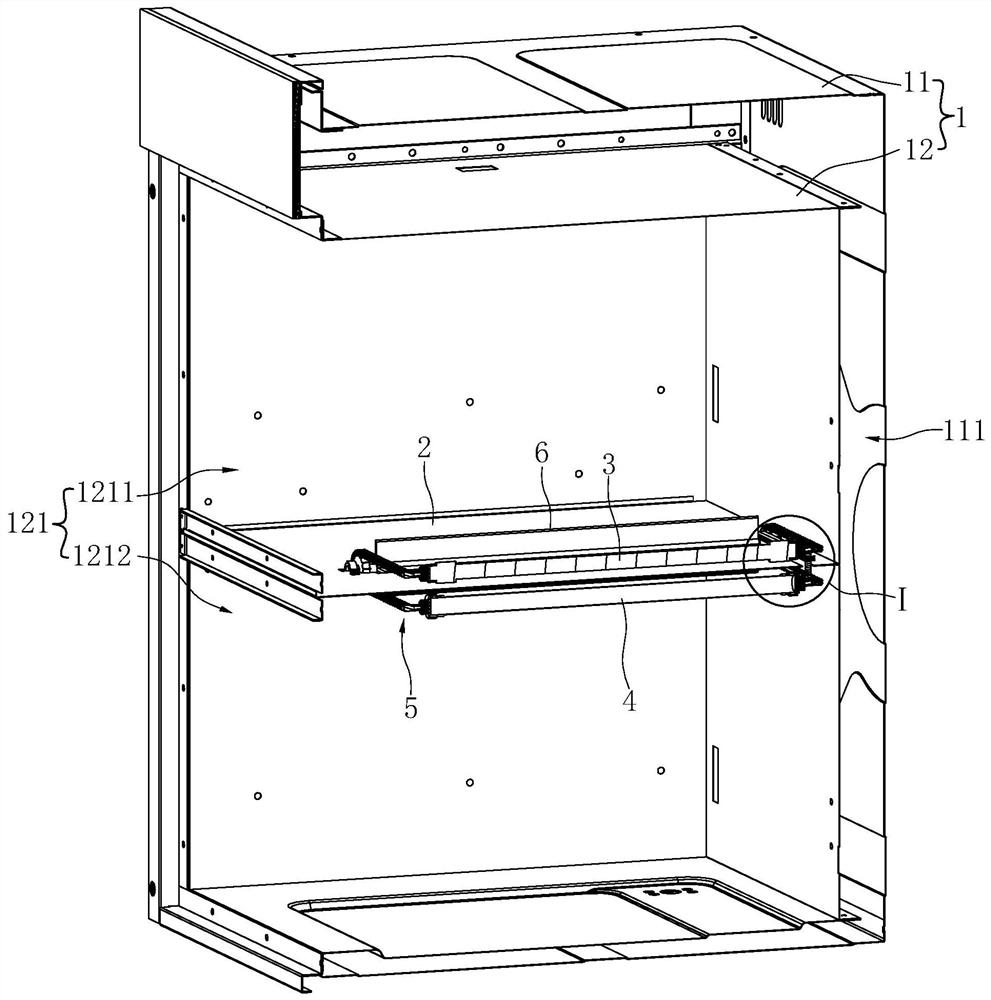
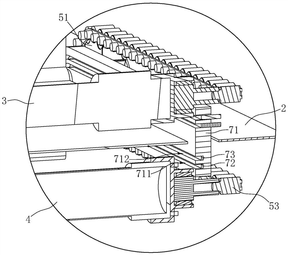
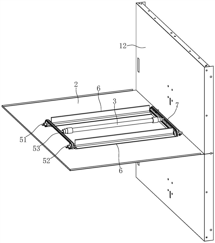
[0049] Such as Figure 1 to Figure 7 Shown is the first preferred embodiment of the layered disinfection cabinet of the present invention. The layered disinfection cabinet includes a cabinet body 1 , a partition plate 2 , a first disinfection device 3 , a second disinfection device 4 , a driving mechanism 5 , a shielding member 6 and a conductive device 7 .

[0050] Wherein, the cabinet 1 includes an outer shell 11 and an inner container 12 disposed in the outer shell 11 , the inner container 12 has a disinfection chamber 121 , and an interlayer 111 is formed between the outer wall of the inner container 12 and the inner wall of the outer shell 11 .

[0051] The partition plate 2 is basically arranged horizontally in the middle of the disinfection chamber 121, and divides the disinfection chamber 121 into a first chamber 1211 located above and a second chamber 1212 located below; An elongated opening 21 extending along the depth direction of the disinfection chamber 121 is op...

Embodiment 2

[0065] Such as Figure 8 Shown is the second preferred embodiment of the layered disinfection cabinet of the present invention. The difference with Example 1 is:

[0066] In this embodiment, the conductive device 7 is replaced by a conductive flexible wire 7'. The number of the flexible wires 7' is two, and they are installed on the top surface and the bottom surface of the partition plate 2 respectively. The first flexible wire 7' of the two flexible wires 7' One end is electrically connected to the power supply of the layered disinfection cabinet, and the second end is electrically connected to the terminals of the first disinfection device 3 and the second disinfection device 4 respectively. Since the length of the flexible wire 7' is constant, the driving mechanism 5 needs to drive the first sterilizing device 3 and the second sterilizing device 4 to move back and forth instead of moving in one direction all the time. In this embodiment, a conductive spring is used as th...


PUM

PropertyMeasurementUnit
Wavelengthaaaaaaaaaa

Abstract

The invention discloses a layered disinfection cabinet. The layered disinfection cabinet comprises a cabinet body (1) with a disinfection chamber (121), a partition plate (2) arranged in the disinfection chamber (121) for dividing the disinfection chamber (121) into a first chamber (1211) and a second chamber (1212) and a first disinfection device (3) and a second disinfection device (4) positioned in the disinfection chamber (121). The layered disinfection cabinet is characterized in that an opening (21) capable of communicating the first chamber (1211) and the second chamber (1212) is formedin the partition plate (2), and the first disinfection device (3) and the second disinfection device (4) can penetrate through the opening (21) to move opposite to the partition plate (2). Compared with the prior art, disinfection modes of the layered disinfection cabinet can be switched.

Description

technical field [0001] The invention relates to the technical field of kitchen equipment, in particular to a layered disinfection cabinet. Background technique [0002] In the existing layered disinfection cabinet, generally the upper layer is ultraviolet and medium and low temperature disinfection, and the lower layer is high temperature disinfection. [0003] For example, the utility model patent "a double-layer sterilization and disinfection cabinet" with the patent application number CN200820009538.9 (the announcement number is CN201197816Y) discloses a double-layer sterilization and disinfection cabinet, including a cabinet body, a disinfection inner cavity, a cabinet door, And the control circuit, there are 2 disinfection inner chambers, one of which is equipped with a sterilization device that can generate ozone and / or ultraviolet rays, and the other disinfection inner chamber is equipped with 2 or more disinfection devices according to the scope of sterilization The...

Claims


Application Information

Patent Timeline
IPC IPC(8): A61L2/20A61L2/10A61L2/04A61L2/26A47L19/00A61L101/10
CPCA47L19/00A61L2/04A61L2/10A61L2/202A61L2/26A61L2202/12A61L2202/13
Inventor 张文龙
Owner NINGBO FOTILE KITCHEN WARE CO LTD
Why Eureka
Try Eureka