
Anti-regurgitation artificial heart valve
An artificial heart valve and anti-reflux technology, applied in the field of medical devices, can solve the problems of the convenience of positioning the native valve leaflet and the limitation of anchoring stability, and achieve excellent ductility and radial mechanical properties, small alignment deviation, and extension. good effect
Patent Information
- Authority / Receiving Office
- CN · China
- Patent Type
- Applications(China)
- Current Assignee / Owner
- Publication Date
- 2022-01-07
Smart Images
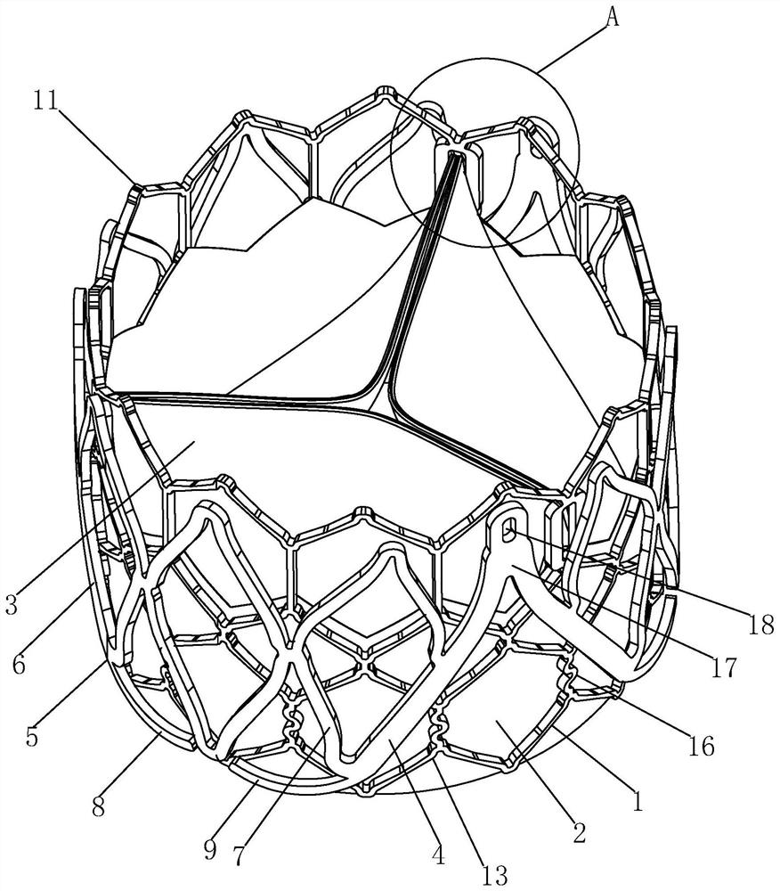
Figure 1 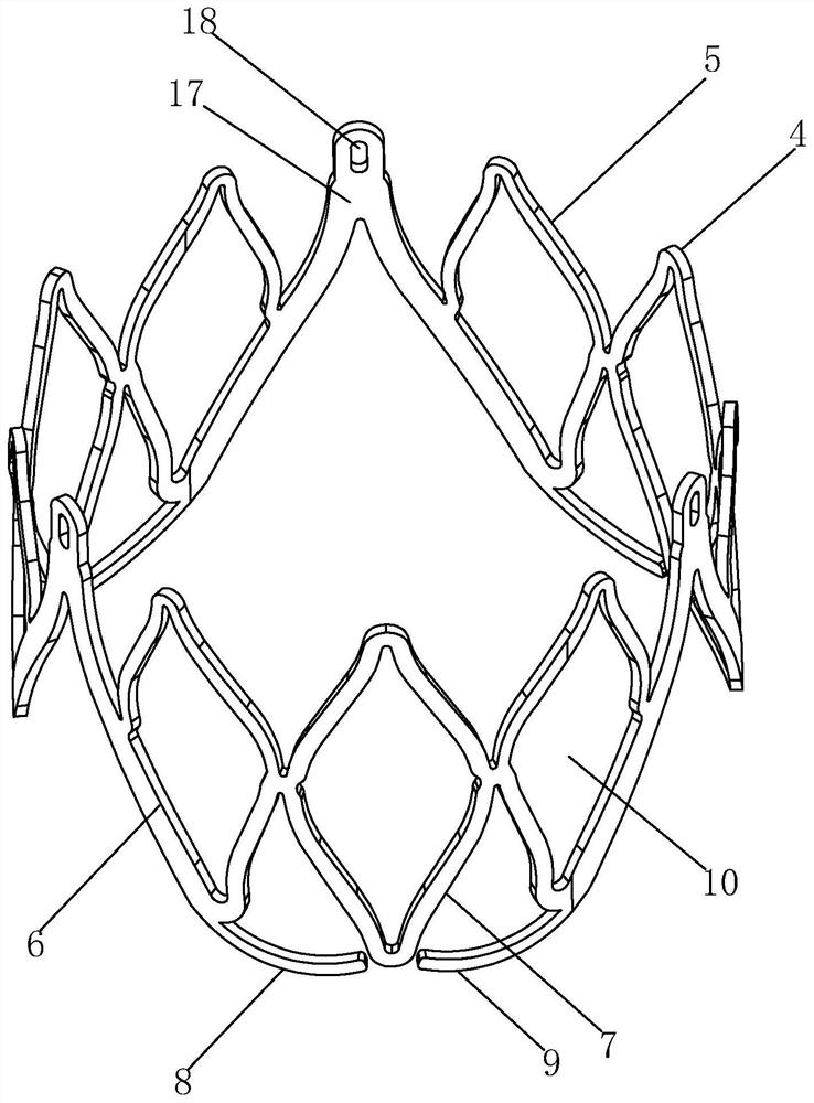
Figure 2 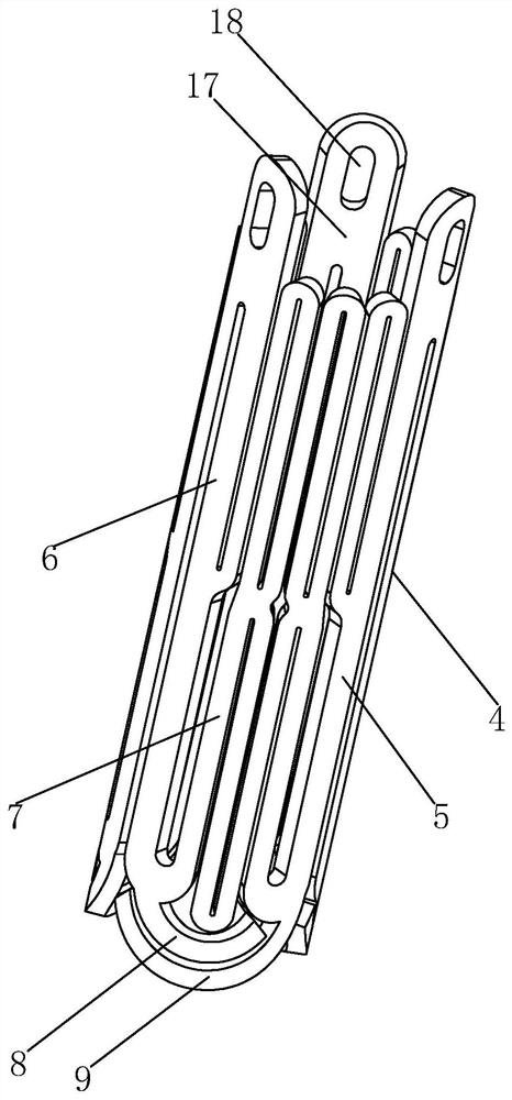
Figure 3
Abstract
Description
technical field
[0001] The invention relates to the field of medical devices, in particular to an anti-reflux artificial heart valve. Background technique
[0002] Aortic valve disease is a common heart valve disease, in which the prevalence of aortic regurgitation and aortic stenosis ranks second and third among all heart valve diseases, and increases with age, 65 years old In the above elderly population, the prevalence of aortic valve disease is as high as 3%. Symptomatic severe aortic stenosis and regurgitation have a very poor prognosis in the natural course of the disease. The two-year survival rate is 50%, and the five-year survival rate is only 20%. Valve replacement surgery is an effective treatment. Many symptoms, poor left ventricular function and unable to withstand traditional surgical thoracotomy.
[0003] In recent years, transcatheter valve implantation / repair has gradually matured and been widely used. In particular, transcatheter aortic valve implantation...
Examples
Embodiment Construction
[0026] Below in conjunction with specific embodiment, content of the present invention is described in further detail:
[0027] combine Figure 1 to Figure 6 , the present embodiment is an anti-reflux artificial heart valve, comprising a tubular stent 1, a skirt cloth 2 coated on the inner surface of the tubular stent 1, three artificial valve leaflets 3 fixed inside the tubular stent 1, and sleeved on the tubular stent. The anti-reflux ring 4 on the outside of the stent 1, the anti-reflux ring 4 includes three anchoring parts 5, and the anchoring parts 5 are used to extend into the original leaflet anti-reflux ring 4 and limit the position.
[0028] in:
[0029] The anti-reflux ring 4 is ring-shaped in a natural state, and is formed by connecting three anchoring parts 5 end to end. One inner rib 7, the first bottom rib 8 and the second bottom rib 9 extended from the lower ends of a pair of side ribs 6, the side ribs 6 are inclined from top to bottom towards the middle of th...