Automobile roof camera lifting system

A technology of cameras and automobiles, applied in vehicle parts, transportation and packaging, etc., can solve the problem of small field of view and achieve the effect of adjusting the field of view

Active Publication Date: 2022-01-07
CHANGSHA UNIVERSITY OF SCIENCE AND TECHNOLOGY
View PDF13 Cites 0 Cited by
  • Summary
  • Abstract
  • Description
  • Claims
  • Application Information

AI Technical Summary

Problems solved by technology

[0004] The present invention aims at the problem that the adjustable field of view of the existing car roof camera raising system is small, and provides a car roof camera raising system with a large adjustable field of view. The specific implementation plan is as follows

Method used


Image

  • Automobile roof camera lifting system
  • Automobile roof camera lifting system
  • Automobile roof camera lifting system

Examples


Embodiment 1

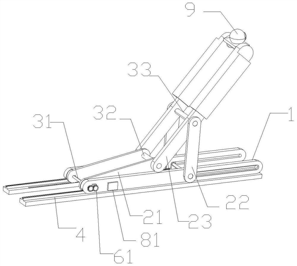
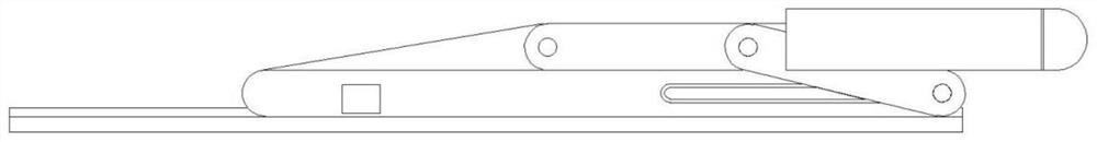
[0051] refer to figure 1 As shown, the present embodiment provides a car roof camera lifting system, including a camera 9, a lifting device, a drive mechanism, two slide rails 1 arranged in parallel and two rails 4 arranged in parallel; in this embodiment, The track 4 is fixed on the roof of the car, and the slide rail 1 is arranged in parallel with the track 4. The length direction of the slide rail 1 and the track 4 is the direction of the front of the car - the rear of the car. The rear direction; the height direction described below refers to the bottom-roof direction.

[0052] Specifically, refer to Figure 5 , the slide rail 1 includes a drive shaft installation hole 11, a first drive motor installation slot 12, a second drive motor installation slot 13, a bar-shaped slot 15 extending along its length direction, and a bar-shaped slot located below the bar-shaped slot 15. 15 communicated channels; the lifting device includes a first rod body 21, a second rod body 22 and...

Embodiment 2

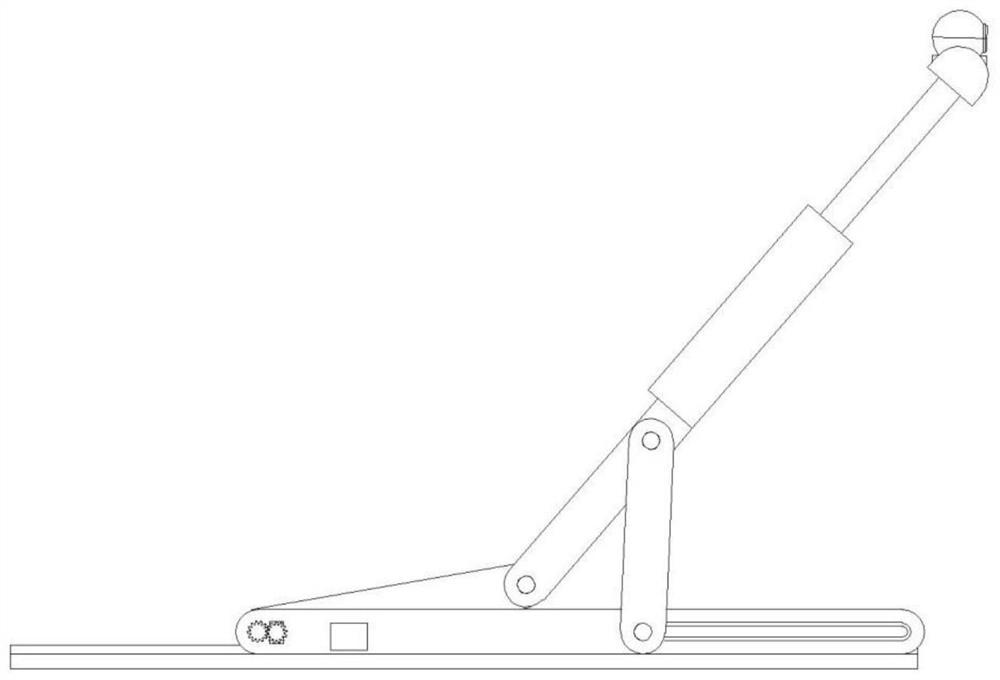
[0064] This embodiment is a further improvement on the basis of Embodiment 1. A telescopic rod 5 is arranged between the third rod body 23 and the camera 9, and the telescopic rod 5 can expand and contract along the length direction of the third rod body 23; the telescopic rod 5 Expand, camera 9 can be further raised.

[0065] The camera 9 is rotatably connected to the telescopic rod 5 through the third rotating shaft 33 , and the camera 9 can adjust the field of view in time as the third rotating shaft 33 rotates according to the surveyed ground conditions. By arranging the telescopic rod 5, the third rotating shaft 33 and the roof camera raising system, the adjustable field of view is further increased.

Embodiment 3

[0067] This embodiment is a further improvement on the basis of Embodiment 1 or 2. The slide rail 1 also includes a third drive motor mounting groove 14; the rail 4 is also provided with a first groove parallel to the second groove 42 Groove 41; the third drive mechanism includes a third drive motor 81 and a roller, the third drive motor 81 is installed in the third drive motor installation groove 14, and the roller is located between the track 4 and the slide rail 1, The roller is connected with the third drive motor 81 , and the roller can roll in the first groove 41 .

[0068] When working, the third drive motor 81 starts, and the rollers roll along the length direction of the first groove 41 along with the third drive motor 81, thereby driving the lifting device to move along the length direction of the track 4, and the roof camera lifts the system belt The adjustable field of view is further increased.


PUM


Abstract

The invention relates to a camera support used during driving, in particular to an automobile roof camera lifting system which comprises a camera, a lifting device, a first driving mechanism, a second driving mechanism and two sliding rails arranged in parallel. The lifting device comprises a first rod body, a second rod body and a third rod body which are arranged in parallel. One end of the third rod body is rotatably connected with the first rod body through a first rotating shaft, and the other end is rotatably connected with the second rod body through a second rotating shaft; the first rod body is rotatably connected with the sliding rail, and the first driving mechanism drives the first rod body to rotate; the second driving mechanism comprises a moving shaft, the second rod body is connected with the moving shaft, the second driving mechanism drives the second rod body to move in the length direction of the track, and the second rod body is rotationally connected with the sliding rail through the moving shaft; the camera is connected with the end, away from the first rod body, of the third rod body. The automobile roof camera lifting system provided by the invention can realize a relatively large adjustable view field range.

Description

technical field [0001] The invention relates to a camera bracket used when driving, in particular to a car roof camera lifting system. Background technique [0002] With the development of social economy, the number of private cars is also increasing year by year, and cars bring great convenience to people's lives. However, there are blind spots in the vision and potential safety hazards during the driving process of the car, such as the car cannot see the road ahead on the uphill section, and the large vehicle in front blocks the traffic lights. Due to the presence of blind spots in the field of vision, it is impossible to respond in time when an emergency occurs, which may easily cause traffic accidents. Therefore, it is necessary to provide a car roof camera raising system. [0003] The traditional car roof camera lifting device is mainly used to survey the road conditions when the vehicle stops moving. The camera will shake during the driving process, and the informati...

Claims


Application Information

Patent Timeline
Patent Type & Authority Applications(China)
IPC IPC(8): B60R11/04
CPCB60R11/04B60R2011/0092B60R2011/0084B60R2011/0085B60R2011/004
Inventor 李奇奇张友才胡林邹铁方
Owner CHANGSHA UNIVERSITY OF SCIENCE AND TECHNOLOGY
Why Eureka
Try Eureka