Unlock instant, AI-driven research and patent intelligence for your innovation.

Mapping circuits

a technology of circuits and circuits, applied in the field of electrical power, can solve the problems of time-consuming, no technology, and inability to provide information about voltage, amperage, power consumption, voltage peaks or any other characteristic that might be relevant,

Active Publication Date: 2018-08-21
INT BUSINESS MASCH CORP
View PDF45 Cites 3 Cited by
  • Summary
  • Abstract
  • Description
  • Claims
  • Application Information

AI Technical Summary

Problems solved by technology

This approach requires no technology, but it is very time consuming.
Also, this method does not provide information about voltage, amperage, polarity, power consumption, voltage peaks or any other characteristic that might be relevant.
While this second approach can detect a circuit for one outlet, it is not practical for multiple outlets on multiple circuits.
This is because the detectors do not differentiate between the signals sent from two different signal modules.
Thus, if an electrician was to plug in multiple modules, and they were on different circuits, there would be no way to differentiate between the modules / outlets.
This approach allows a technician to collect signals from multiple modules in parallel, but this approach is cumbersome, requiring that the outlets and circuit box be connected by an additional wire (“umbilical cord”) that needs to be carried around the worksite.
Moreover, this approach is expensive, due to the computer and the umbilical cord.
This method is limited by the scalability of the number of connections that can be made simultaneously to the fuse box.
Currently, keeping track of outlets to circuit relationships on a large scale requires significant manual work.
Relating the circuit identification for each outlet to the map requires manual work.
Relating circuit identifications to the circuit box requires manual work.
Moreover, current mapping methods do not relate a circuit box representation and a floor plan to provide a comprehensive circuit map.

Method used


Image

  • Mapping circuits
  • Mapping circuits
  • Mapping circuits

Examples


Embodiment Construction

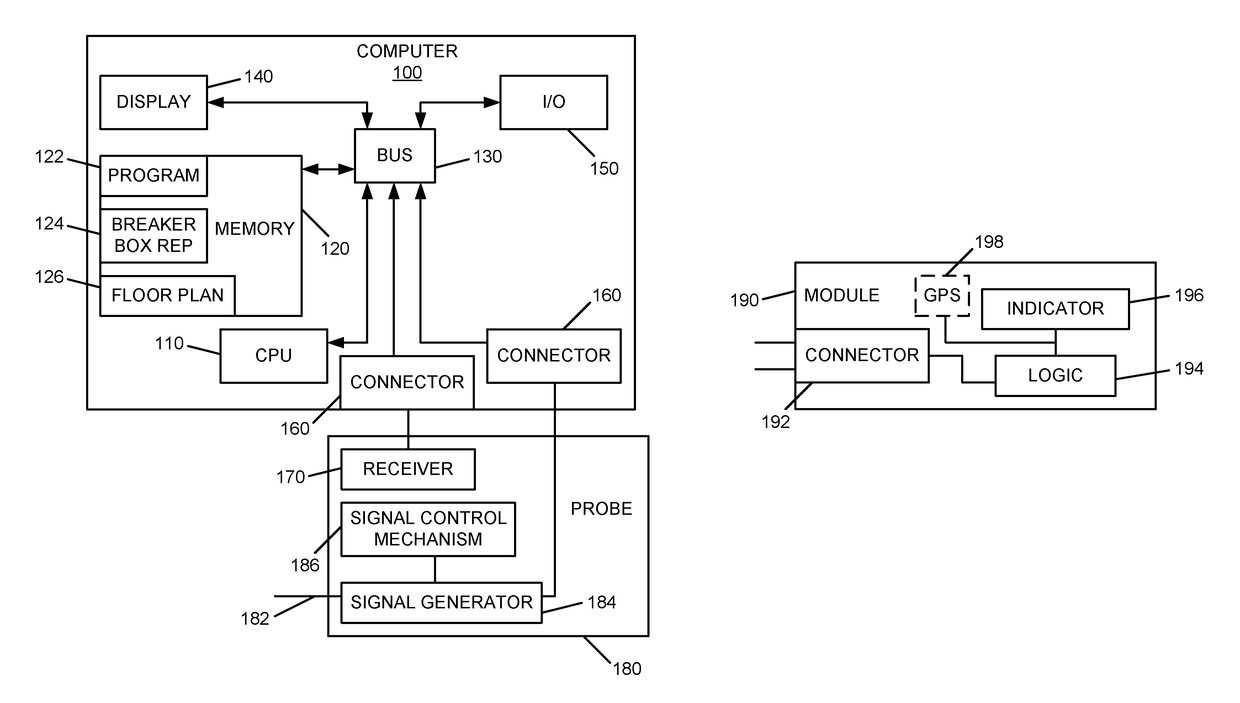
[0021]According to an exemplary embodiment, the present invention provides a method, apparatus and program product for mapping electrical circuits. As shown in FIG. 1, an exemplary apparatus comprises a computer 100 executing a program of instruction 122 and a probe 180 interconnected to the computer 100.

[0022]The computer 100 may be a personal computer (PC) a hand held computing device such as a personal digital assistant (PDA) or any other computer or computing device suitable for executing an interactive program of instruction 122 and displaying representations of a breaker box 124 and a floor plan 126 or other record of one or more rooms.

[0023]In an exemplary embodiment, computer 100 comprises a processing unit 110 interconnected with a memory 120. Processing unit 110 and memory 120 may be interconnected through a bus 130 or any other suitable means for electronic interconnection. A display 140 and one or more input / output devices 150 may also be interconnected with the processi...


PUM


Abstract

A probe is adapted to send a signal over a selected circuit and to provide circuit information. One or more modules have a connector for electrically connecting to an outlet, logic interconnected with the connector for detecting the signal and receiving the circuit information, and an indicator interconnected with the logic for presenting the circuit information in response to the signal. A computer is operably associated with the probe and configured to execute a program of instructions to provide a breaker box representation and an electronic record of one or more rooms showing outlet symbols that identify the location of outlets. The computer is configured to execute the program of instructions to collect the circuit information from the one or more modules and to associate the circuit information with a corresponding breaker on the breaker box representation and on outlet symbols on the electronic record of one or more rooms.

Description

FIELD OF THE INVENTION[0001]The invention relates to the field of electrical power and more particularly to a system method and program product for mapping electrical circuits.BACKGROUND[0002]Electricians typically require a variety of information about outlets before performing work on them, such as replacing an outlet, adding a new outlet to a circuit, and other electrical work. An electrician might use a variety of tools to acquire the necessary information. This information may include the circuit number that an outlet is on, and possibly the outlet number and other information such as voltage, amperage, polarity, and the like. The electrician might also like to collect information such as the amount of power consumed over a period of time, voltage peaks, and other relevant electrical information about the outlet and / or the circuit.[0003]Circuits are currently mapped using one of two methods. The first method is to flip the switches on a circuit breaker while a second person wai...

Claims


Application Information

Patent Timeline
Patent Type & Authority Patents(United States)
IPC IPC(8): G01R15/00G01R19/25G01R31/04G06F17/50
CPCG06F17/5004G01R31/045G01R19/2513G01R31/69G06F30/13
Inventor CALCATERRA, JEFFREY A.GUTIERREZ-RIVAS, HUMBERTOMILLER, STEVEN M.
Owner INT BUSINESS MASCH CORP