Passive and active stereo vision 3D sensors with variable focal length lenses

a 3d sensor, passive technology, applied in the field of passive and active stereo vision 3d sensors with variable focal length lenses, can solve the problems of introducing noise through ambient light, affecting the quality of 3d imaging,

Active Publication Date: 2020-02-04
MICROSOFT TECH LICENSING LLC
View PDF77 Cites 5 Cited by
  • Summary
  • Abstract
  • Description
  • Claims
  • Application Information

AI Technical Summary

Problems solved by technology

However, contamination of ambient light in the reflected light / images can degrade the 3D imaging quality.
Additionally, brightly illuminated environments, such as outdoor environments during daylight, can also introduce noise through ambient light.

Method used


Image

  • Passive and active stereo vision 3D sensors with variable focal length lenses
  • Passive and active stereo vision 3D sensors with variable focal length lenses
  • Passive and active stereo vision 3D sensors with variable focal length lenses

Examples


Embodiment Construction

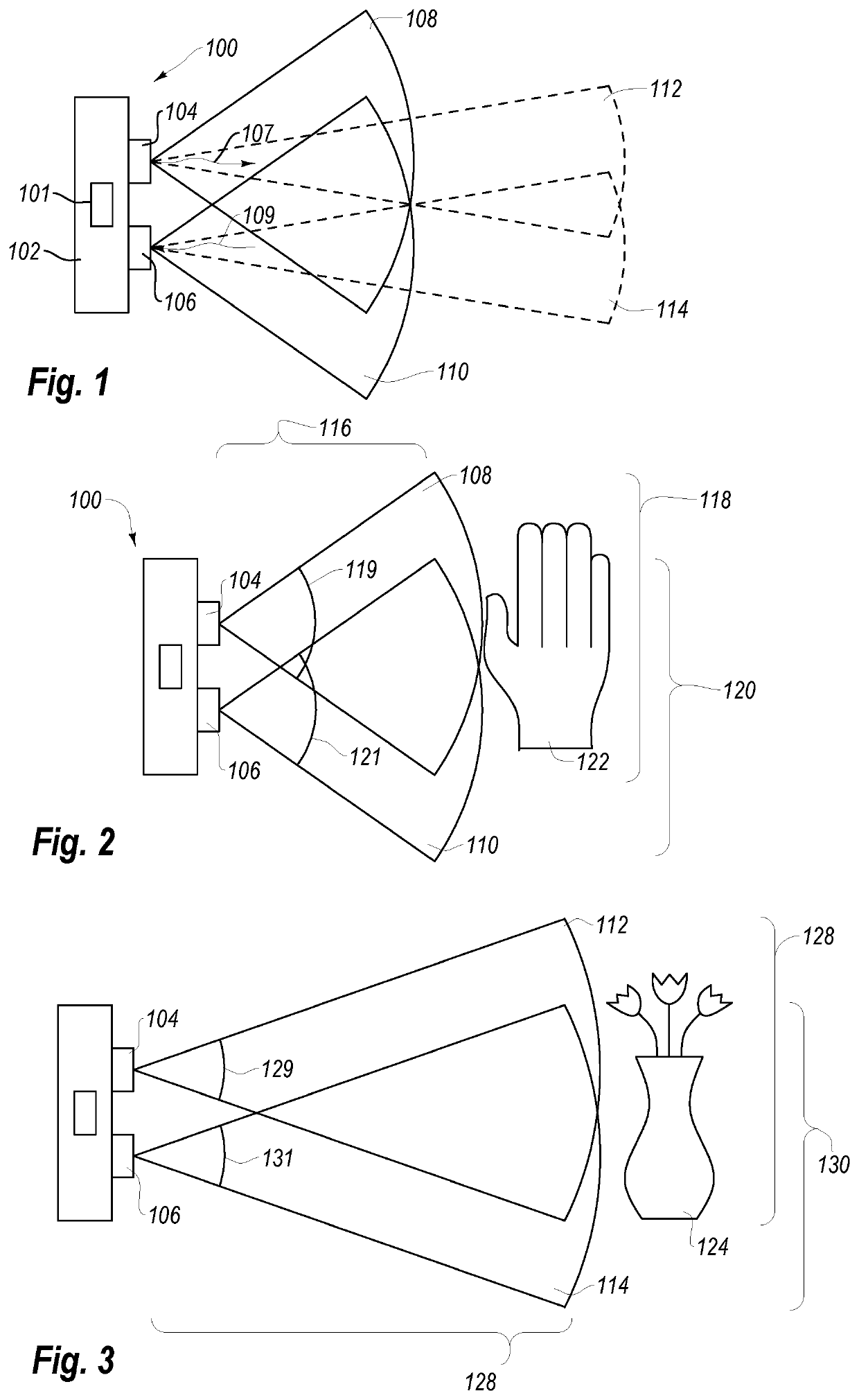
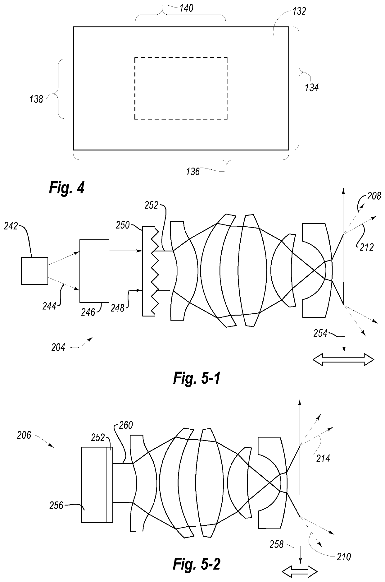
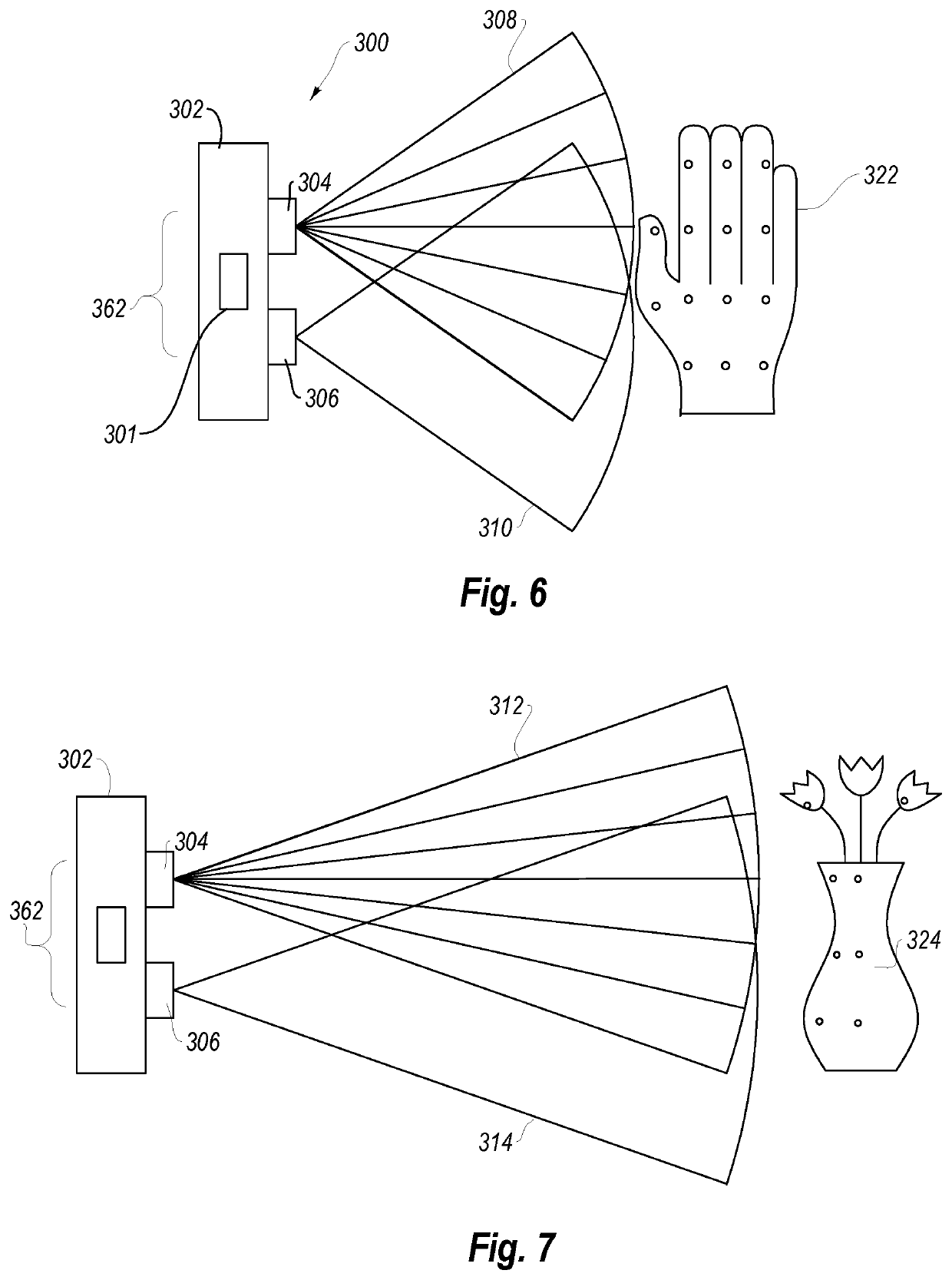
[0031]Disclosed embodiments include improved imaging systems, as well as devices, systems, and methods for improving efficiency and resolution in three-dimensional (3D) imaging.

[0032]With regard to the following disclosure, it will be appreciated that in the development of the disclosed embodiments), as in any engineering or design project, numerous embodiment-specific decisions will be made to achieve the developers' specific goals, such as compliance with system-related and business-related constraints, which may vary from one embodiment to another. It will further be appreciated that such a development effort might be complex and time consuming, but would nevertheless be a routine undertaking of design, fabrication, and manufacture for those of ordinary skill having the benefit of this disclosure.

[0033]In some embodiments, the accuracy by which a target and / or an environment may be imaged with a 3D imaging system may be at least partially related to ratio of reflected light (ligh...


PUM


Abstract

A stereoscopic 3D imaging system includes multiple imaging sensors with adjustable optics. The adjustable optics are variable to alter the FOV of each of the multiple imaging sensors to improve angular resolution of the imaging system.

Description

CROSS-REFERENCE TO RELATED APPLICATIONS[0001]N / ABACKGROUNDBackground and Relevant Art[0002]Three-dimensional (3D) imaging systems use configured to identify and map a target based on light that is reflected from the target. Many of these imaging systems are configured with a light source that is configured to emit light towards the target a photoreceptor to receive the light after it is reflected back from the target.[0003]Some imaging systems (i.e., time-of-flight imaging systems) are capable of identifying the distances and positions of objects within a target environment at any given time by measuring the elapsed time between the emission of light from the light source and the reception of the light that is reflected off of the objects.[0004]Other imaging systems (e.g., structured light systems) measure the distortion or displacement of light patterns to measure the shapes, surfaces and distances of the target objects. For instance, light may be emitted as a structured pattern, s...

Claims


Application Information

Patent Timeline
Patent Type & Authority Patents(United States)
IPC IPC(8): H04N13/00H04N13/254H04N5/232G06K9/20G06K7/10H04N7/18H04N13/243B64C39/02
CPCG06K7/10554H04N7/181H04N13/243H04N5/23238G06K7/10633H04N7/188H04N13/254B64C39/024G02B19/009G02B5/021G02B5/0278G02B19/0047G02B19/0014G02B19/0076H04N23/698
Inventor PRICE, RAYMOND KIRKDEMANDOLX, DENISBLEYER, MICHAELZHAO, JIAN
Owner MICROSOFT TECH LICENSING LLC
Why Eureka
Try Eureka