Vehicular seat apparatus

a seat and seat cushion technology, applied in the field of seat cushions, can solve the problems of seat sliders or the frame of seat cushions, sensor outputs may possibly be disturbed, entail redundant operations such as attachment and removal of seat cushions from them, and additional costs

Inactive Publication Date: 2005-05-26
NHK SPRING CO LTD +1
View PDF4 Cites 36 Cited by
  • Summary
  • Abstract
  • Description
  • Claims
  • Application Information

AI Technical Summary

Benefits of technology

[0010] Accordingly, the object of the present invention is to provide a vehicular seat apparatus in which left- and right-hand slide rail units can be kept in predetermined positions.

Problems solved by technology

Before the apparatus is attached to the vehicle body, however, the seat slider or the frame of the seat cushion may possibly be deformed under the influence of vibration that acts on the seat apparatus during transportation, for example, the dead weight of the apparatus, etc.
In this case, the sensor outputs may possibly be disturbed with the seat apparatus attached to the vehicle body despite the finished calibration.
With use of this jig, however, it entails redundant operations, such as attachment to and removal of the seat apparatus from it, as well as additional cost.
This variation may possibly cause a phase difference in locking operation between the respective locking mechanisms of the two slide rail units.
Thus, the locking mechanisms of the rail units cannot operate fully synchronously, so that one of the rail units may possibly fail to be fully locked (or may be half-locked, as it is called).

Method used


Image

  • Vehicular seat apparatus
  • Vehicular seat apparatus
  • Vehicular seat apparatus

Examples


Embodiment Construction

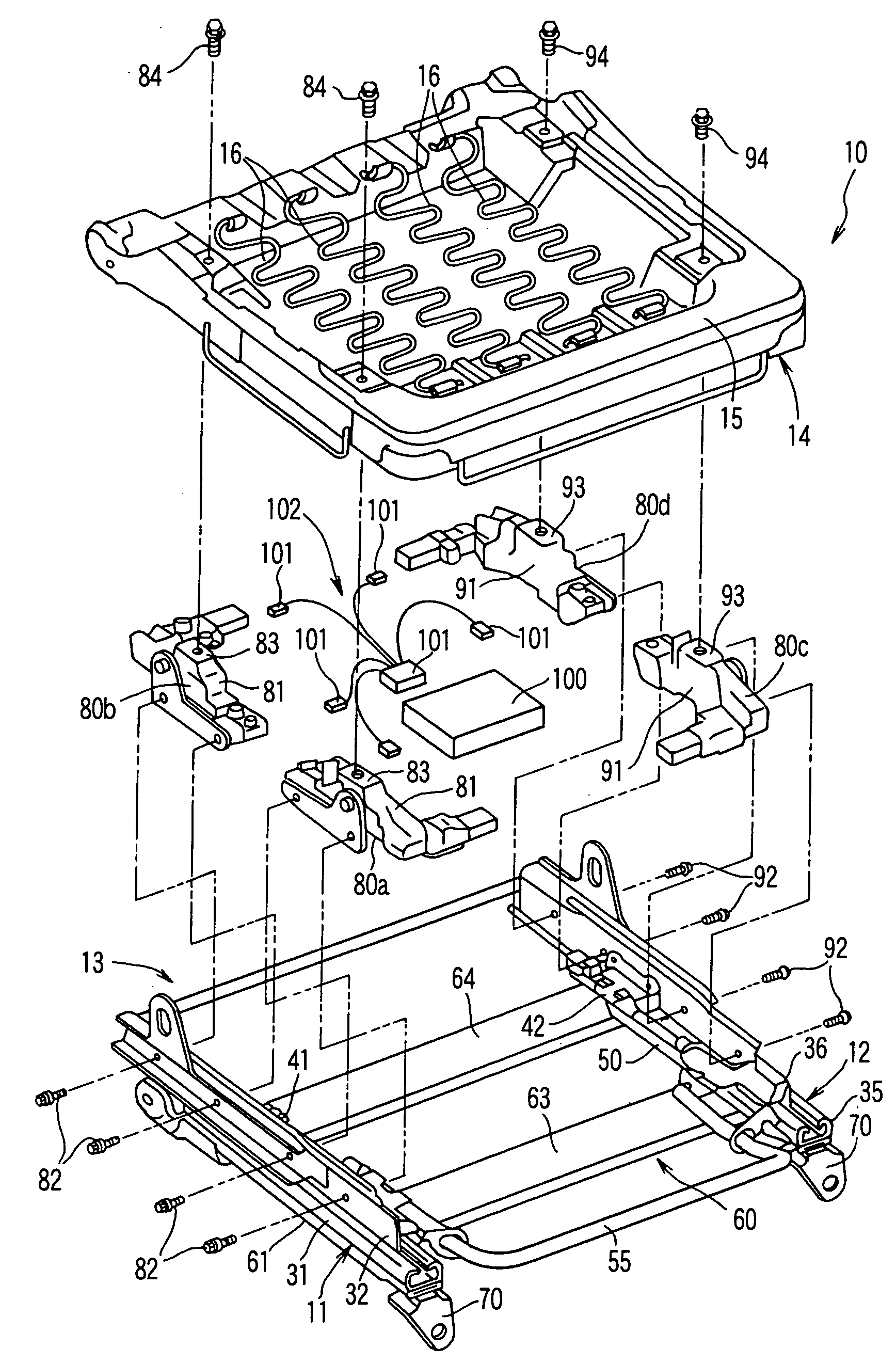
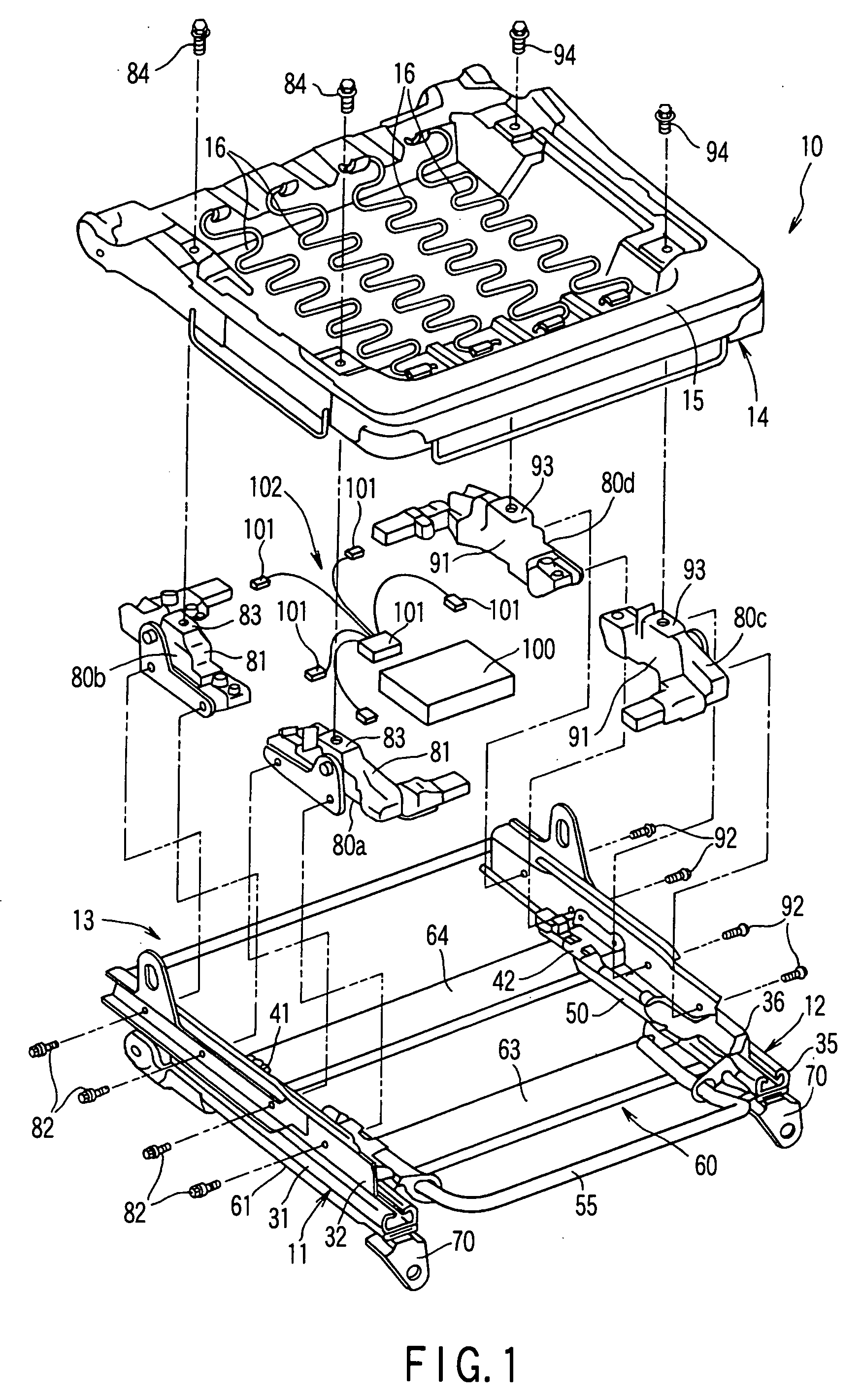
[0023] An embodiment of the present invention will now be described with reference to FIGS. 1 to 4.

[0024] A vehicular seat apparatus 10 shown in FIG. 1 comprises a seat slide device 13, which includes left- and right-hand slide rail units 11 and 12, and a seat cushion assembly 14. The seat cushion assembly 14 is supported by means of the seat slide device 13 so as to be movable in a front-rear direction of a vehicle. The seat cushion assembly 14 is provided with a cushion frame 15 and a spring member 16, such as an S-spring, attached to the frame 15.

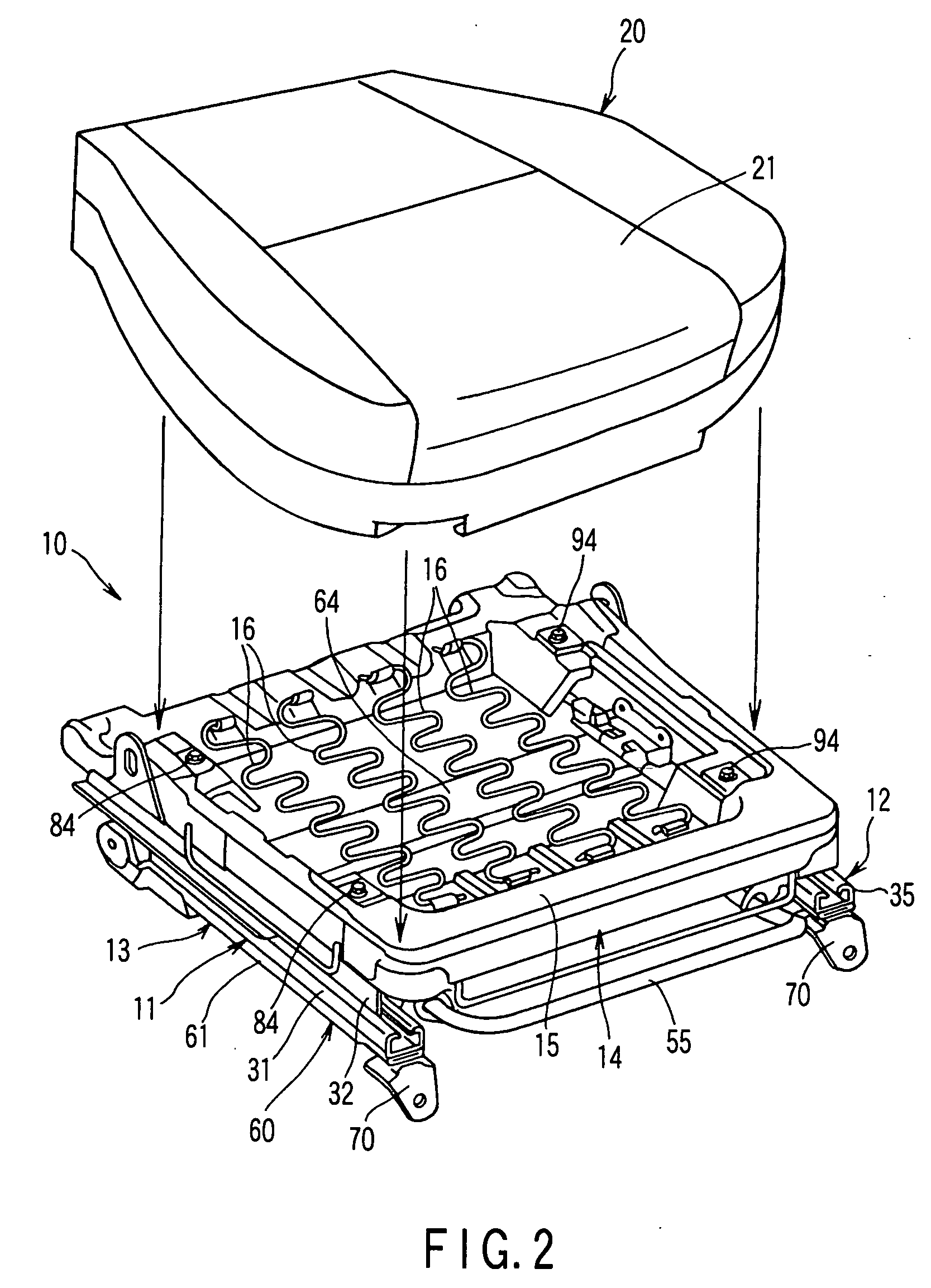
[0025] As shown in FIG. 2, a cover assembly 20 is provided on the top side of the seat cushion assembly 14. An example of the cover assembly 20 is composed of a pad (not shown) and an outer covering 21 of a fabric or the like that covers the pad. The pad is formed of an elastic material such as urethane.

[0026] The seat slide device 13 comprises the first slide rail unit 11 on the left-hand side of FIG. 1 and the second slide rail unit...


PUM


Abstract

A vehicular seat apparatus has a first slide rail unit including a first stationary rail and a first moving rail and a second slide rail unit including a second stationary rail and a second moving rail. Load sensors are provided between the seat cushion assembly and the moving rails. The first stationary rail and the second stationary rail are connected to each other by a rigid frame. The rigid frame can maintain the relative positions of the first and second slide rail units. Body mounting leg portions provided on the rigid frame are fixed to a seat mounting portion of a vehicle body.

Description

CROSS-REFERENCE TO RELATED APPLICATIONS [0001] This application is based upon and claims the benefit of priority from prior Japanese Patent Application No. 2003-363367, filed Oct. 23, 2003, the entire contents of which are incorporated herein by reference. BACKGROUND OF THE INVENTION [0002] 1. Field of the Invention [0003] The present invention relates to a vehicular seat apparatus mounted in a vehicle such as an automobile. [0004] 2. Description of the Related Art [0005] In an automobile that is furnished with an airbag for its passenger seat, the airbag may sometimes be expected to expand if an occupant in the passenger seat is an adult. The automobile of this type must be provided with determining means that determines whether the occupant in the passenger seat is an adult or any other one (child, child seat, or other occupant). Load sensors that are formed of strain gages, for example, are used as the determining means. The load sensors are incorporated in a seat cushion of the ...

Claims


Application Information

Patent Timeline
Patent Type & Authority Applications(United States)
IPC IPC(8): B60N2/07B60N2/42B60N2/08B60N2/68B60R21/16
CPCB60N2/071B60N2/0715B60N2/68B60N2/0843B60N2/0825B60N2/002
Inventor OSAWA, SHIGEYUKIHANDA, MASAMIICHISUGI, MORIHIRO
Owner NHK SPRING CO LTD
Why Eureka
Try Eureka