

Developer supply device and image forming apparatus including the same
- Summary
- Abstract
- Description
- Claims
- Application Information
AI Technical Summary
Benefits of technology
Problems solved by technology
Method used
Image

Examples
Embodiment Construction
[0060] The following will describe an embodiment of the present invention. It is noted that the present invention is by no means limited to this embodiment. The present embodiment illustrates, as an example, a developer supply device such as a toner cartridge which is detachably attached to an electrophotographic image forming apparatus.
[0061] The developer supply device of the present invention prevents troubles such as poor developer supply and pollution on account of a leakage of a developer from occurring, making it possible to stably and properly supply the developer.
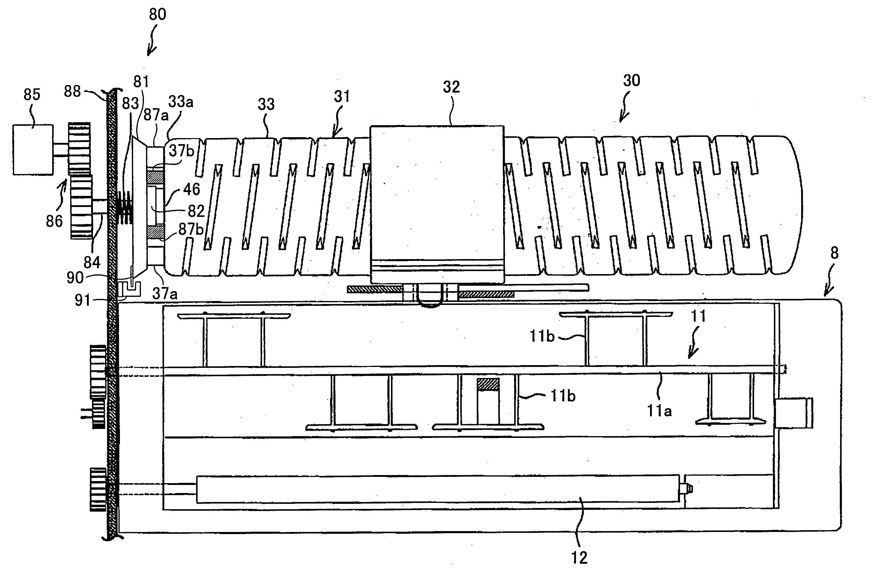
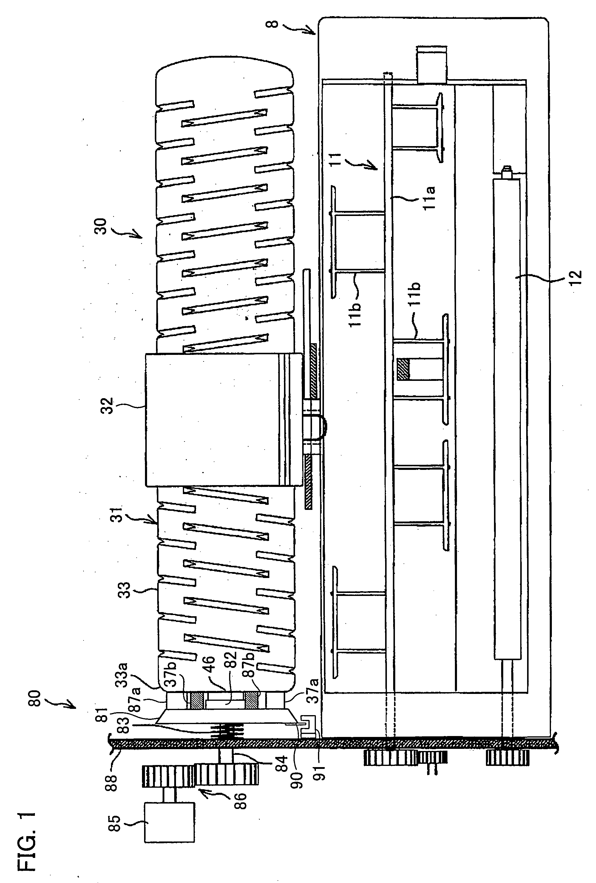
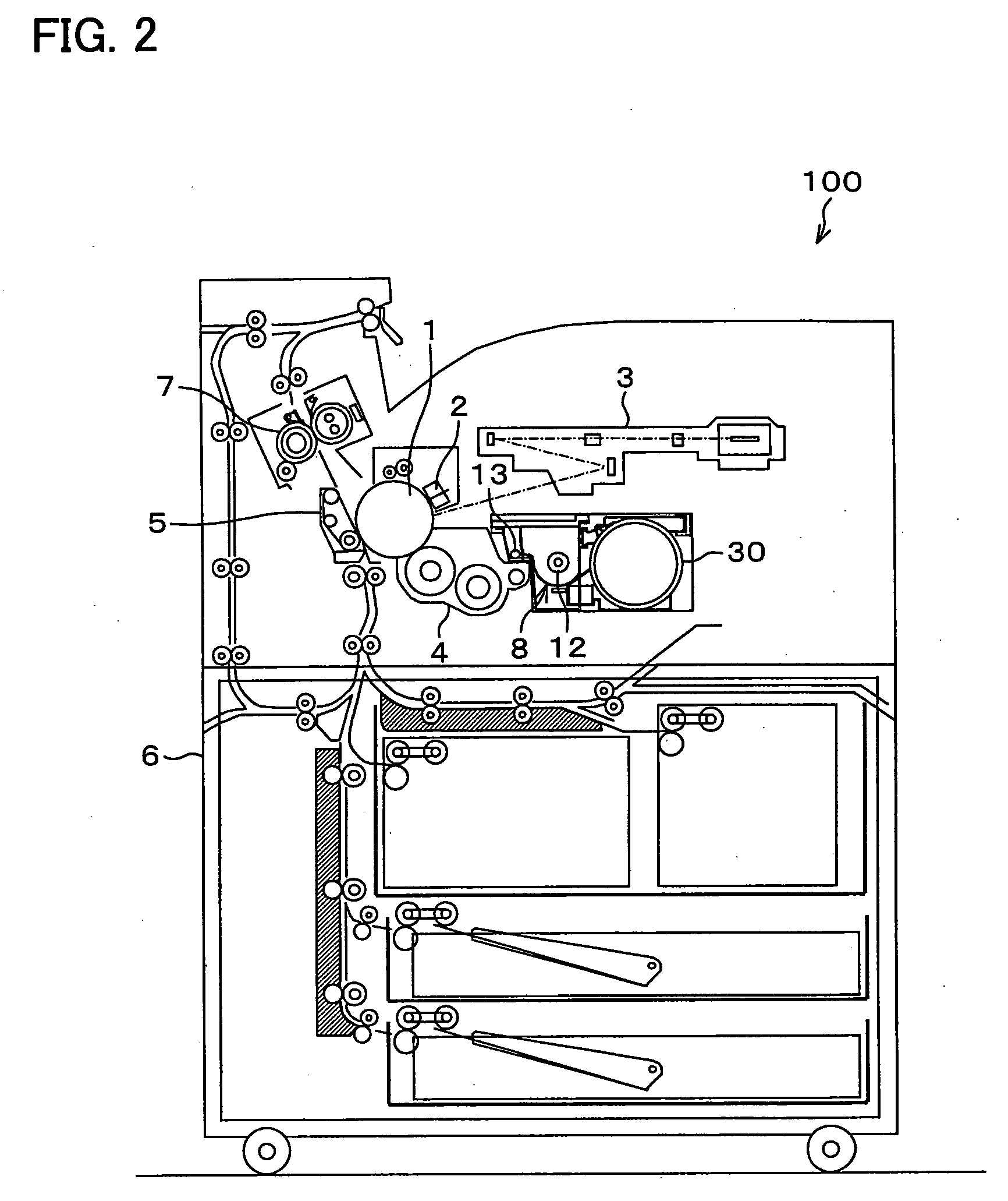
[0062]FIG. 2 is a plan view of a printer (image forming apparatus) 100 including a toner supply device (developer supply device) 30 according to the present embodiment. The toner supply device 30 is detachably provided in the electrophotographic printer 100 shown in FIG. 2. Through a hopper 8, the toner supply device 30 supplies toner (developer) to a developing device 4. The toner may be a two-component toner co...
PUM
 Abstract
Description
Claims
Application Information