Wheel type mechanical instruction switch

Inactive Publication Date: 2006-02-16
ZIPPY TECH
View PDF3 Cites 4 Cited by
  • Summary
  • Abstract
  • Description
  • Claims
  • Application Information

AI Technical Summary

Benefits of technology

[0005] Therefore the primary object of the present invention is to resolve the aforesaid disadvantages. The present invention aims to provide a simple mechanical type conductive contact leg to generate instruction output to replace the conventional button switches. The instruction switch according to the invention includes a wheel and a contact leg driven by the wheel to move to the left or right, and conductive legs located within the left and right moving range of the contact leg so that when the wheel is swayed by forces, the contact leg connects to the conductive leg to generate instruction signals. The structure is simpler and may be fabricated at a lower cost.

Problems solved by technology

However, for lengthy table fields, scroll operation and control cannot fully meet requirements, and the general keyboard does not have corresponding keys to provide transverse movement function.
Such a design does not fully exploit the advantages of the wheel.
The actual product includes a sway seat which makes design more complicated).
Adding the sway seat makes design and fabrication more complicated.
And the size of the mouse cannot be shrunk because of addition of the sway seat and the button switches.
It is only suitable for large mouse products.
The button switch is more expensive.
Moreover, with the prevailing product trend that requests lean and light, adding the button switch is against this trend in terms of the mouse size.
It also cannot be adapted to the keyboard or remote control device that also has a wheel.

Method used


Image

  • Wheel type mechanical instruction switch
  • Wheel type mechanical instruction switch
  • Wheel type mechanical instruction switch

Examples


Embodiment Construction

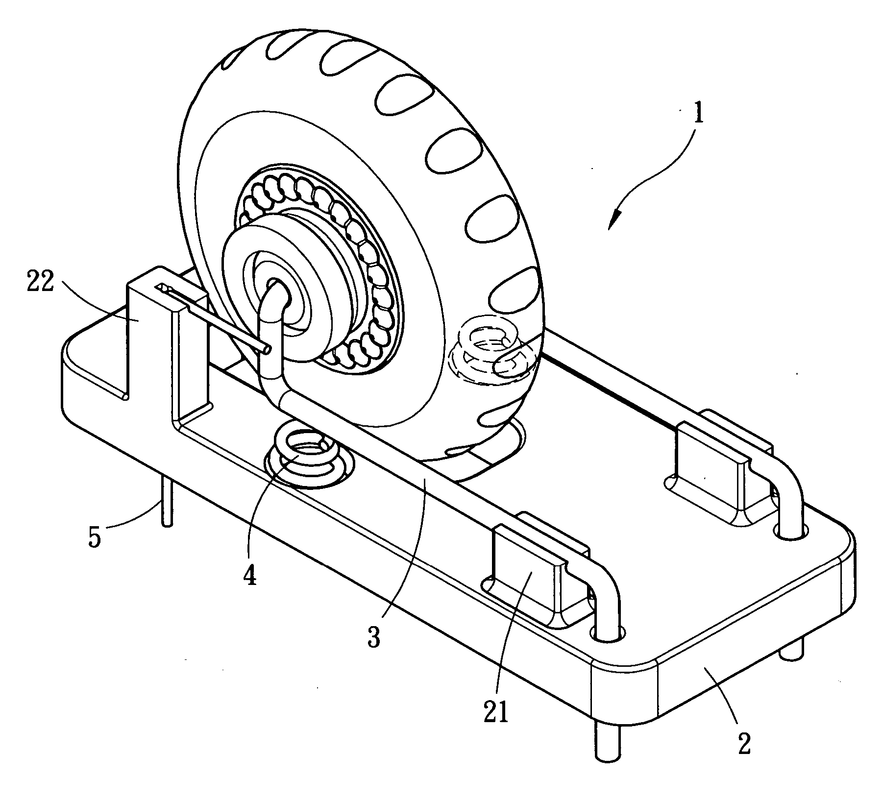
[0017] Please referring to FIGS. 3 and 4, the wheel type mechanical instruction switch according to the present invention is adopted for use on electronic products such as a mouse 10 (referring to FIG. 7), a keyboard 20 (referring to FIG. 8) or a remote control device 30 (referring to FIG. 9) to output different instruction signals. It includes a wheel 1 and a base board 2 corresponding to sway movements of the wheel 1 to generate instruction signals.

[0018] The mechanical instruction switch according, to the invention, in addition to the wheel 1 and the base board 2, also includes a contact leg 3 which has one end fastened to the base board 2 and other end coupled to the wheel 1 and driven by the wheel 1 to move to the left side or the right side for a selected displacement (the left and right side displacements may be formed by transverse movements or sway movements. In the embodiment discussed below, the sway movement is adopted as an example). The other end of the contact leg 3 c...


PUM


Abstract

A wheel type mechanical instruction switch employs a simple mechanical contact leg structure to replace conventional button switches to output instructions. The invention has a wheel coupling with a contact leg which is moveable to the left side and the right side with the movement of the wheel to form a selected displacement, and a conductive leg located respectively within the left and right displacement. When a force sways the wheel, the contact leg is moved to connect to the conductive leg to generate an instruction signal. The structure is easy to fabricate at a lower cost.

Description

FIELD OF THE INVENTION [0001] The present invention relates to a wheel type mechanical instruction switch and particularly to a wheel type mechanical switch adopted for use on electronic devices such as mouses, remote control devices or keyboards to output different instruction signals. BACKGROUND OF THE INVENTION [0002] In the scroll mouse now being commonly used, there is a wheel located between the left and the right function keys to enable users to directly skip pages or text lines through rotation of the wheel when reading lengthy texts (such as novels or presentation data) without depressing the page down key or moving the mouse and cursor to the scroll spots on the right side of the screen to execute page down or skip line operation. Namely, the wheel can replace the scroll function on the right side of the screen to make user operation easier. In R.O.C. patent No. 590292, applicant proposes an improved mouse design. It aims to provide an improved scroll function that has a s...

Claims


Application Information

Patent Timeline
IPC IPC(8): G09G5/08
CPCG06F3/0362G06F3/0213
Inventor CHOU, CHIN-WEN
Owner ZIPPY TECH
Why Eureka
Try Eureka