

Attachment device for attaching slinging or lashing means
a technology for attaching devices and slings, which is applied in the direction of swivels, flexible elements, chain elements, etc., can solve problems such as unsatisfactory known devices, uncontrolled prestressing, and problems such as problems such as arising
Active Publication Date: 2008-06-19
RUD KETTENFABRIK RIEGER & DIETZ GMBH & CO
View PDF9 Cites 5 Cited by
- Summary
- Abstract
- Description
- Claims
- Application Information
AI Technical Summary
Benefits of technology
The invention is an attachment device for slinging or lashing means to articles. The device has a fastening element for attaching it to the article, an attachment element for the slinging or lashing means, and a connecting element that connects the fastening element to the attachment element. The connecting element is mounted on a two-part bushing that encloses the fastening element over part of its length, and it can rotate about the fastening element's axis. The attachment device has a high level of tilting resistance and allows for easy installation.
Problems solved by technology
However, problems may arise if heavy articles are to be turned in addition to being raised.
The third known device is unsatisfactory insofar as it is of complicated construction and the rolling-contact bodies of its axial bearings are subjected to an uncontrolled level of prestressing which depends on the tightening torque of the bolt designed as the fastening element.
Method used
View moreImage
Smart ImageViewing Examples

Examples
Embodiment Construction
[0003]The object of the invention, in the case of an attachment device of the type in question, is to increase the relative movement capability between the fastening element and the connecting element by replacing the sliding mounting with an easy-to-install rolling-contact mounting, a high level of tilting resistance of the connecting element being desired at the same time. This object is achieved, in the case of an attachment device of generic type, in
Login to View More PUM
 Abstract
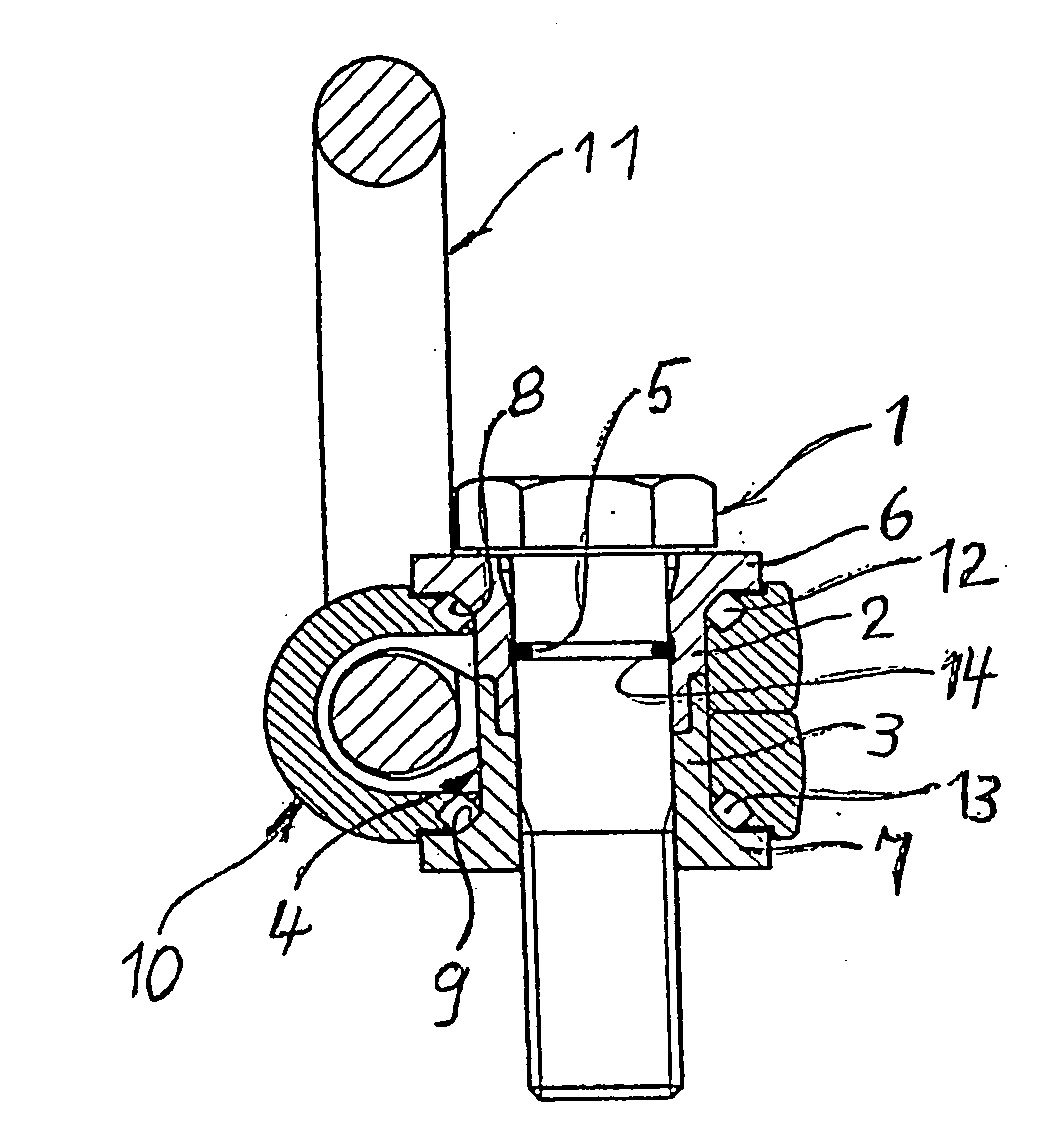
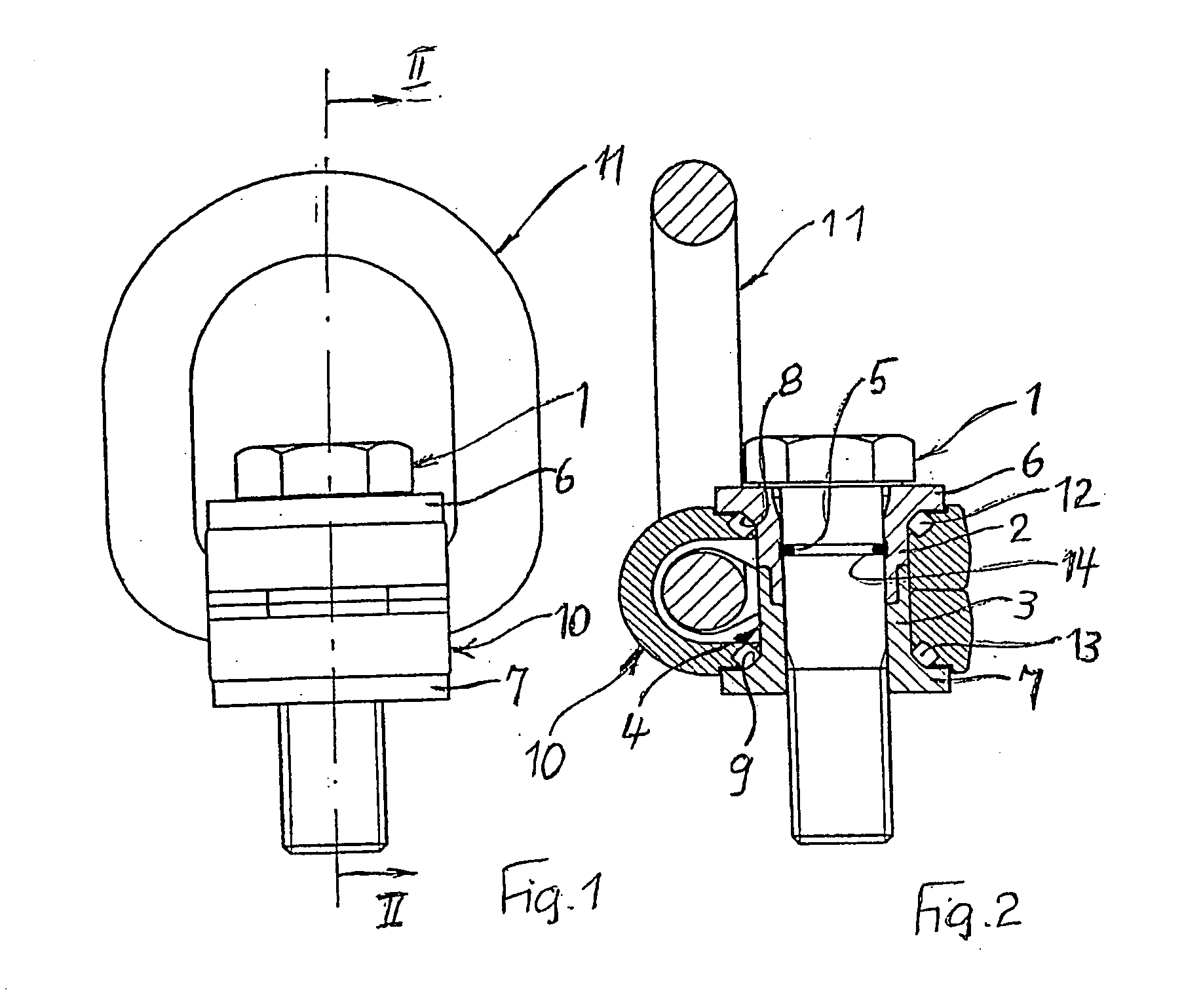
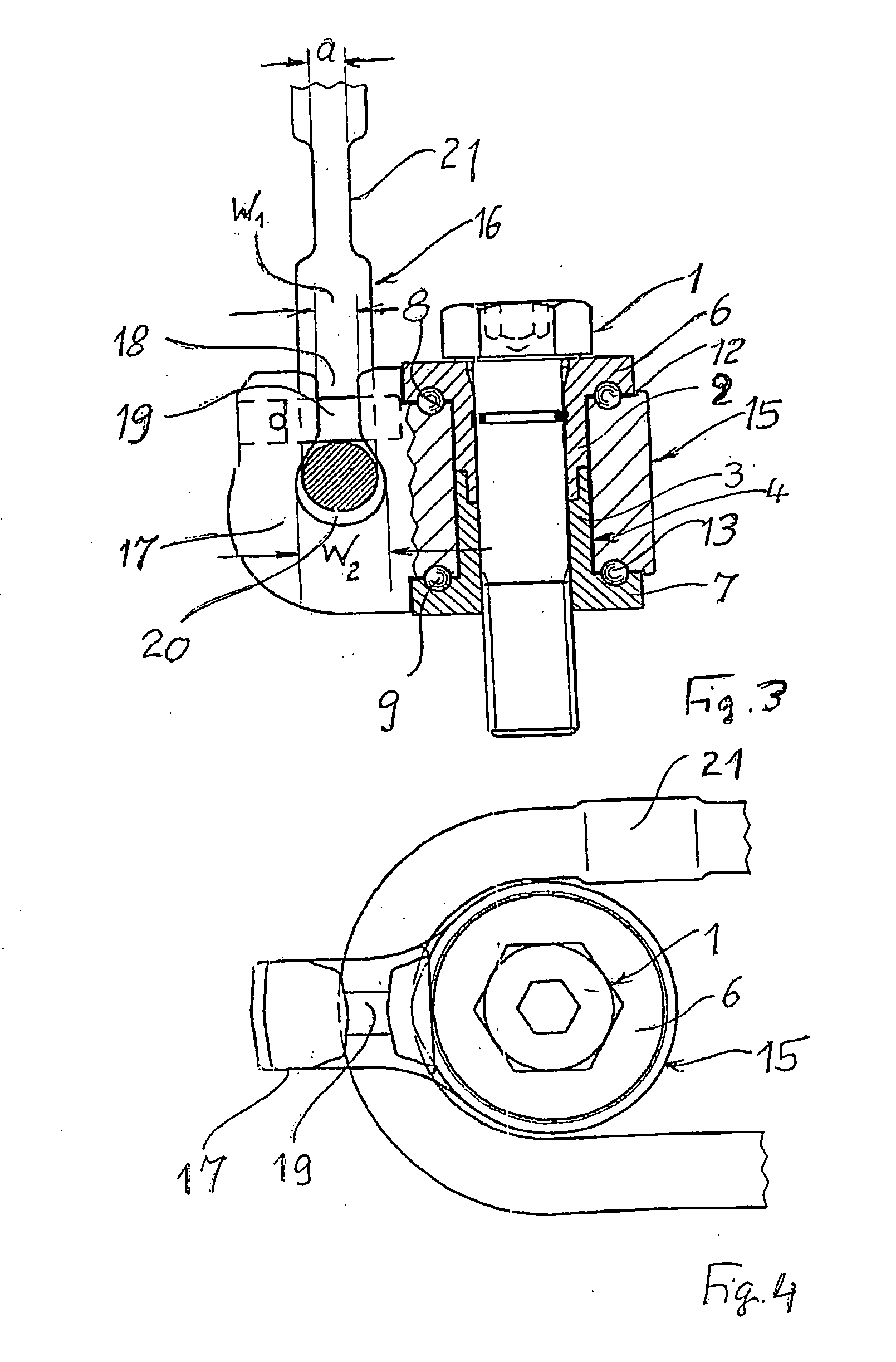
Disclosed is an attaching device for attaching stopping or lashing means to objects that are to be transported or tied down, comprising a fixing element (1), an attaching element (16), and a connecting element (15) which is rotatably mounted on a socket (4) wrapped around the fixing element (1) and connects the attaching element (16) to the fixing element (1). The connecting element (15) leans against ring flanges (6, 7) placed at the ends of the socket (4) via series of rolling bodies (12, 13) so as to allow said connecting element (15) to rotate without jerking and make it sufficiently tilt-proof.
Description
TECHNICAL FIELD[0001]The invention relates to an attachment device for attaching slinging or lashing means to articles which are to be transported or lashed, having a fastening element which serves for fastening the same on the respective article and is formed by a bolt, having an attachment element for the slinging or lashing means, and having a connecting element which connects the fastening element to, the attachment element, is mounted, such that it can be rotated about the longitudinal axis of the fastening element, on a two-part bushing enclosing the fastening element over part of its length, and has its axial position on the bushing secured by annular flanges arranged at opposite ends of the bushing.PRIOR ART[0002]An attachment element of the abovementioned type is known from DE 10013845 A1. In the case of the known device, the connecting element is mounted with a sliding fit on a bushing which comprises two parts, of which the facing end surfaces butt against one another. Th...
Claims
Login to View More Application Information
Patent Timeline
 Patent Type & AuthorityApplications(United States)
IPC IPC(8): B61D45/00B66C1/66F16C11/04F16G15/00F16G15/08
CPCB66C1/66Y10T403/32975F16G15/08F16G15/00
InventorSMETZ, REINHARD
OwnerRUD KETTENFABRIK RIEGER & DIETZ GMBH & CO