Suction device

a suction device and suction tube technology, applied in the field of suction devices, can solve the problems of high transportation costs in dispatch, comparatively large spatial requirements, and detrimental to the overall cost-effectiveness of the device, and achieve the effect of simplifying the assembly of the suction devi

a suction device and suction tube technology, applied in the field of suction devices, can solve the problems of high transportation costs in dispatch, comparatively large spatial requirements, and detrimental to the overall cost-effectiveness of the device, and achieve the effect of simplifying the assembly of the suction devi

US20080250600A1Inactive Publication Date: 2008-10-16SCHWEPPACH FAB VON HOLZBEARBEITUNGSMASCHINEN GMBH

Image

  • Suction device
  • Suction device
  • Suction device

Examples


Embodiment Construction

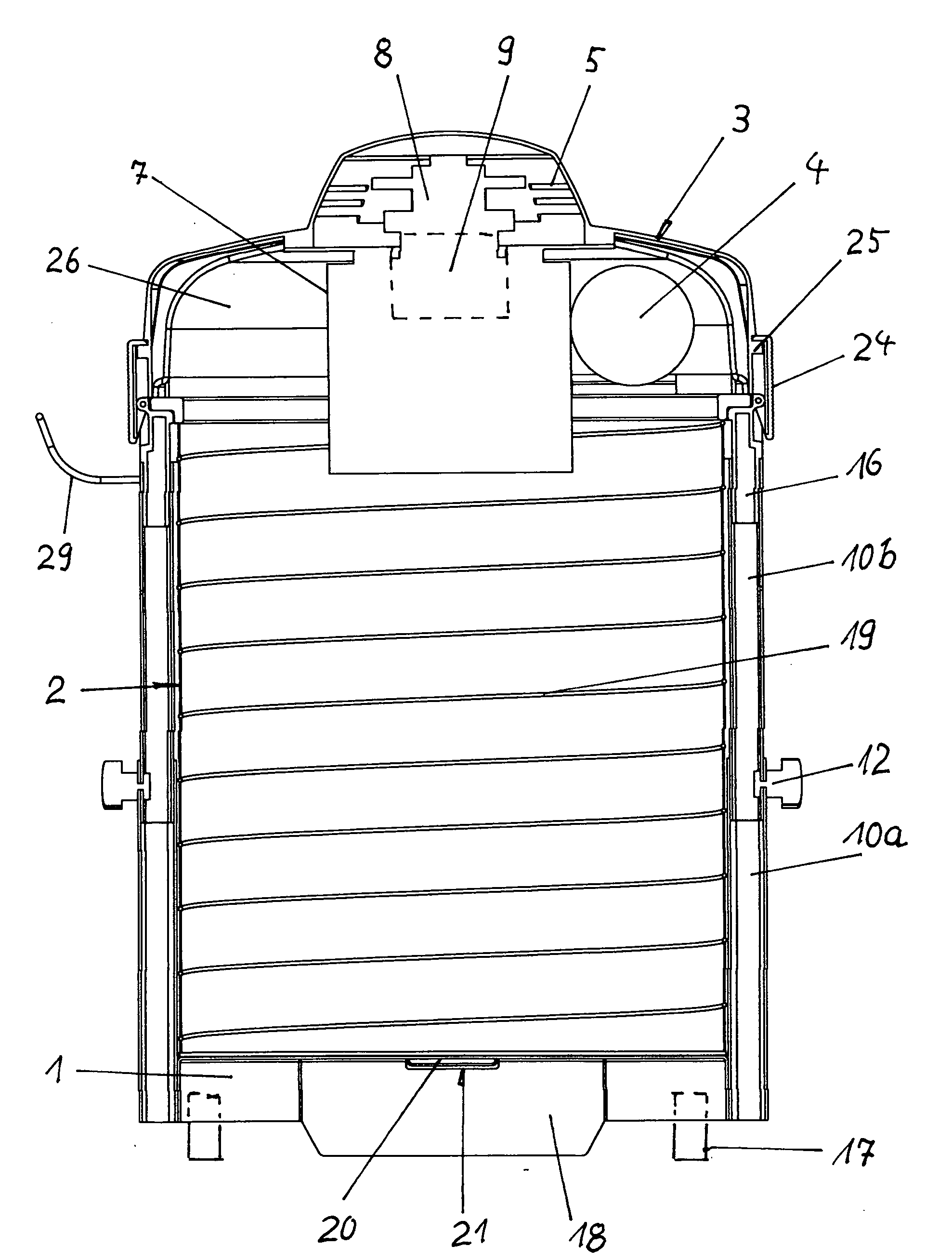
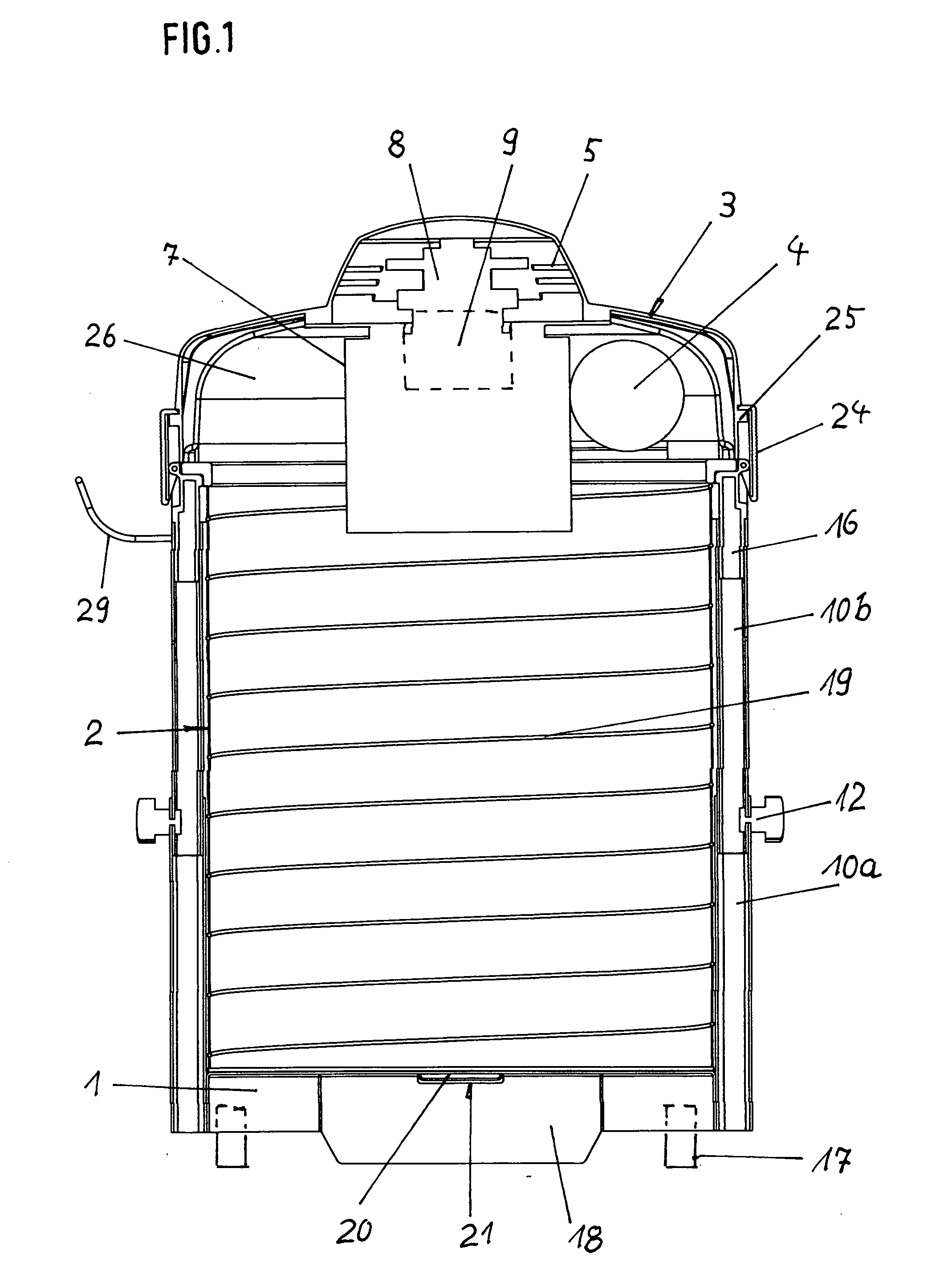
[0016]FIG. 1 is a vertical section through a suction device according to the invention,

[0017]FIG. 2 is an exploded view of the arrangement according to FIG. 1 and

[0018]FIG. 3 is a view corresponding to FIG. 2 of a further exemplary embodiment of the suction device according to the invention.

[0019]The main field of application of the invention is formed by suction devices for professional use such as for workshops and / or building sites and the like.

DESCRIPTION OF PREFERRED EMBODIMENTS

[0020]The suction device showed in the Figures contains a lower part 1 which is provided with rollers, a collection container 2 resting on said lower part and an upper part 3 which can be placed onto said collection container from above, is provided with grips and which can be used to close the upper opening in the collection container 2. The suction device has an air inlet 4 which opens into the collection container and an air outlet 5. The air inlet 4 and the air outlet 5 are associated with the upper ...


PUM


Abstract

In a suction device for the intake by suction and / or extraction by suction of chips or dust, comprising a lower part (1) which is preferably provided with rollers (17), a collection container (2) which can be placed on said lower part and an upper part (3) which closes said collection container and has a motor-drivable fan (9) and a filter cartridge (7) which separates said fan from the interior of the collection container (2), an air inlet (4) which opens into the collection container (2) and is provided with a connector (6) and an air outlet (5) which is arranged downstream of the fan (9) being provided, a low transport volume can be achieved in a simple manner as a result of the fact that there is arranged between the lower part (1) and upper part (3) a support means which is configured in the manner of a telescope and with which there is associated a means (14) for receiving the upper end region of the collection container (2), the axial length of which is variable and the base of which can be secured to the lower part (1).

Description

FIELD OF THE INVENTION[0001]The invention relates to a suction device, in particular a workshop suction device, for the intake by suction and / or extraction by suction of chips and / or dust, comprising a lower part which is preferably provided with rollers, a collection container which can be placed on said lower part and an upper part which closes said collection container and has a motor-drivable fan and a filter cartridge which separates said fan from the interior of the collection container, an air inlet which opens into the collection container and is provided with a connector and an air outlet which is associated with the fan being provided.BACKGROUND OF THE INVENTION[0002]In the know arrangements of this type, the collection container is configured as a cup-like shaped part. This shaped part is rigid per se and thus defines the height of the device in all cases. This therefore gives rise to a comparatively high transport volume, leading not only to high transportation costs in ...

Claims


Application Information

Patent Timeline
16 Oct 2008
Publication
US20080250600A1
IPC
A47L9/10; A47L5/22; B62B3/00
CPC
A47L5/365; A47L7/0085; A47L9/00; A47L9/0027; A47L9/0036; A47L9/009; A47L9/1683
Inventors
WINDRICH, WOLFGANG