Input apparatus, control apparatus, control system, electronic apparatus, and control method

a control apparatus and input technology, applied in the field of input apparatus, control apparatus, control system, electronic apparatus, and control method, can solve the problems of poor operation feeling and poor operation feeling, and achieve the effect of improving the operation feeling of scrolling an imag

Active Publication Date: 2010-07-01
SONY CORP
View PDF22 Cites 29 Cited by
  • Summary
  • Abstract
  • Description
  • Claims
  • Application Information

AI Technical Summary

Benefits of technology

[0015]In the embodiment of the present invention, since the ratio of the first movement amount to the second movement amount is changed, a scroll direction of the image can be biased in directions such as a horizontal-axis direction and a vertical-axis direction on the screen. As a result, an image can be prevented from being scrolled in a direction unintended by a user on the screen, with the result that an operational feeling for the user in scrolling an image can be improved.
[0075]As described above, according to the embodiments of the present invention, an input apparatus, a control apparatus, a control system, an electronic apparatus, and a control method that are capable of improving an operational feeling in scrolling an image displayed on a screen can be provided.

Problems solved by technology

In this case, however, since the input apparatus is operated in space without any guide, there is a problem that a scroll direction of the image on the screen is not settled if a movement of the input apparatus is converted into scroll as it is, thus leading to a poor operational feeling.
If the movement of the input apparatus is converted into scroll as it is in this case, the image on the screen is scrolled in a direction unintended by the user, thus resulting in a problem of a poor operational feeling.

Method used


Image

  • Input apparatus, control apparatus, control system, electronic apparatus, and control method
  • Input apparatus, control apparatus, control system, electronic apparatus, and control method
  • Input apparatus, control apparatus, control system, electronic apparatus, and control method

Examples


first embodiment

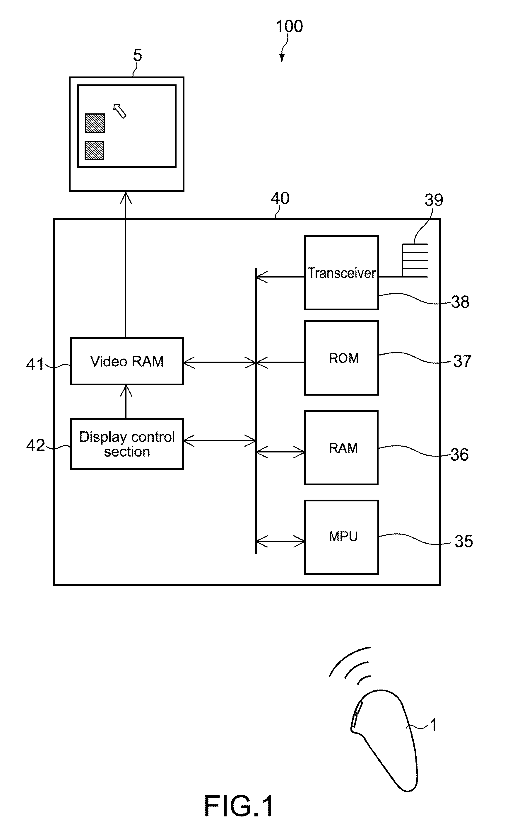
[0106]FIG. 1 is a diagram showing a control system according to a first embodiment of the present invention. A control system 100 includes a display apparatus 5, a control apparatus 40, and an input apparatus 1.

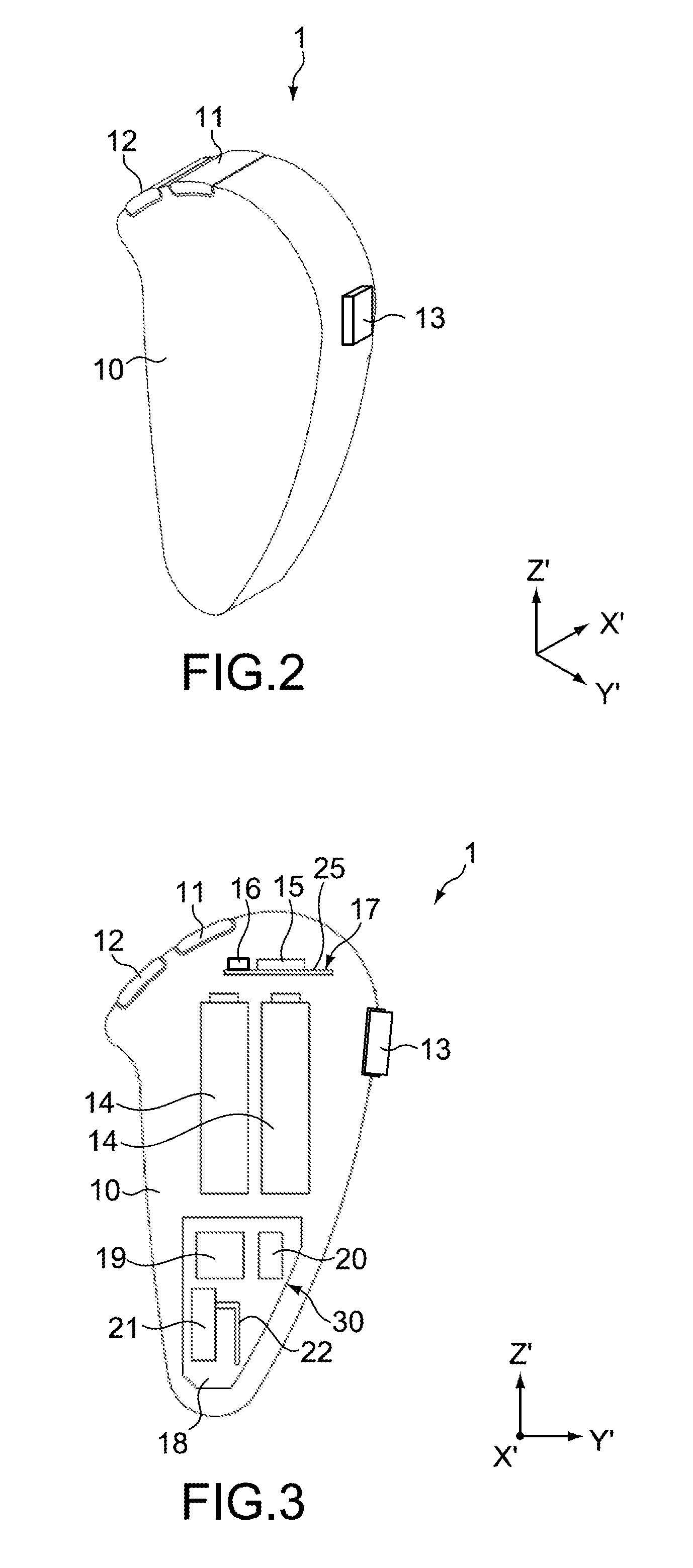
[0107]FIG. 2 is a perspective diagram showing the input apparatus 1. The input apparatus 1 is of a size that a user is capable of holding. The input apparatus 1 includes a casing 10. Further, the input apparatus 1 includes an operation section 23 (see FIG. 6) including a button 11 and a button 12 adjacent to the button 11 that are provided at a center of an upper portion of the casing 10, and a button 13 provided at a side portion of the casing 10.

[0108]Typically, the buttons 11, 12, and 13 are each a press-type button. The operation section 23 is not limited to the press-type button, and a bar-type operation section that is operated with one end as a fulcrum, or a slide-type operation section may also be used. Each of the buttons 11, 12, and 13 includes a built-in switch (no...

second embodiment

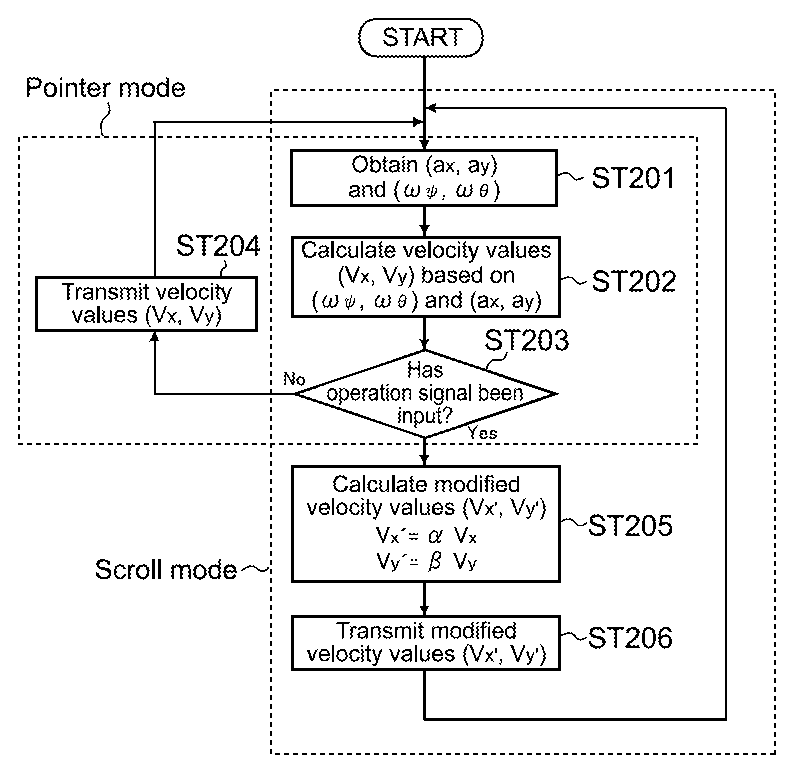
[0177]Next, a second embodiment of the present invention will be described. The first embodiment above has described a case where the scroll direction is biased in (restricted to) a uniaxial direction of one of the horizontal-axis direction and the vertical-axis direction on the screen 3. The second embodiment is different from the first embodiment in that the scroll direction is biased in (restricted to) biaxial directions of the horizontal-axis direction and the vertical-axis direction on the screen 3. Therefore, that point will mainly be described.

[0178]FIG. 12 is a flowchart showing an operation of the input apparatus 1 according to the second embodiment.

[0179]As shown in FIG. 12, in Steps 301 to 304, processes that are the same as those of Steps 201 to 204 of FIG. 10 are executed. In other words, when judged that the button 13 is not pressed (NO in Step 303), information on velocity values is transmitted from the input apparatus 1 (Step 304), and the pointer 2 displayed on the ...

third embodiment

[0190]Next, an input apparatus according to a third embodiment of the present invention will be described.

[0191]The third embodiment mainly describes points different from those of the second embodiment above.

[0192]FIG. 14 is a flowchart showing an operation of the input apparatus 1 according to the third embodiment.

[0193]As shown in FIG. 14, in Steps 401 to 404, processes that are the same as those of Steps 301 to 304 of FIG. 12 are executed. In this case, by the user operating the input apparatus 1 3-dimensionally in a state where the button 13 is not pressed, the pointer 2 moves on the screen 3 in accordance with the 3-dimensional operation.

[0194]When the button 13 is pressed, an operation signal is output from the switch provided to the button 13 and input to the MPU 19 (YES in Step 403). Upon being input with the operation signal, the MPU 19 calculates a tilt angle ξ of a combined vector of the first velocity value and the second velocity value using Equation (5) below (Step 40...


PUM


Abstract

An input apparatus includes a detection section, a change section, and a transmission section. The detection section detects a movement amount of a user operation in an arbitrary direction. The change section changes a ratio of a first movement amount as a movement amount in a first operation direction corresponding to a first direction on a screen to a second movement amount as a movement amount in a second operation direction corresponding to a second direction on the screen different from the first direction, the first movement amount and the second movement amount corresponding to a detection value detected by the detection section. The transmission section transmits the first movement amount and the second movement amount whose ratio has been changed as scroll information of an image displayed on the screen.

Description

BACKGROUND OF THE INVENTION[0001]1. Field of the Invention[0002]The present invention relates to an input apparatus for operating a GUI (Graphical User Interface), a control apparatus for controlling the GUI in accordance with information transmitted from the input apparatus, a control system including those apparatuses, an electronic apparatus, and a control method.[0003]2. Description of the Related Art[0004]Pointing devices, particularly a mouse and a touchpad, are used as controllers for GUIs widely used in PCs (Personal Computers). Not just as HIs (Human Interfaces) of PCs of the related art, the GUIs are now starting to be used as interfaces for AV equipment and game machines used in living rooms etc. with, for example, televisions as image media. Various pointing devices that a user is capable of operating 3-dimensionally are proposed as controllers for the GUIs of this type (see, for example, Japanese Patent Application Laid-open No. 2001-56743 (paragraphs (0030) and (0031),...

Claims


Application Information

Patent Timeline
Patent Type & Authority Applications(United States)
IPC IPC(8): G06F3/048G06F3/0485G06F3/0481
CPCG06F3/0346G06F3/0484G06F3/0485G06F3/04815G06F3/03
Inventor SAWAI, KUNIHITOYAMAMOTO, KAZUYUKI
Owner SONY CORP
Why Eureka
Try Eureka