Container Assembly for Storing Peripheral Computer Memory Devices

a technology for computer memory devices and containers, applied in containers, recording carrier construction details, applications, etc., can solve problems such as not providing proper accommodating space, and achieve the effect of improving the reliability of computer peripheral storage and tidiness of computer peripherals

Inactive Publication Date: 2011-07-14
HELM BURGERHOFF BRIGITTE
View PDF6 Cites 2 Cited by
  • Summary
  • Abstract
  • Description
  • Claims
  • Application Information

AI Technical Summary

Benefits of technology

[0005]The first objective of the present invention is to provide a container assembly that allows a plurality of such container assemblies to be mutually engaged by inserting first raised portions into corresponding first depressed portions and second raised portions into corresponding second depressed portions at the outer surfaces of the container assemblies so that a stacked arrangement of container assemblies (vertically and / or transversely stacked) may be achieved, thus improving tidiness and accessibility of the computer peripherals contained in the container assemblies.
[0006]The second object of the present invention is to provide such a container assembly that, when a front cover thereof is pressed, a base is disengaged and moved to project from the housing of the container assembly to allow to conveniently place, remove or arrange the computer peripherals. After pushing the base back into the housing the base comes into a secured position within the housing again. The structure and operation of the container assembly not only provides convenience but also improves the reliability of the storage of the computer peripherals.

Problems solved by technology

Since these general boxes or desk drawers are not specially designed for computer peripherals, they do not provide proper accommodating space therefore.

Method used


Image

  • Container Assembly for Storing Peripheral Computer Memory Devices
  • Container Assembly for Storing Peripheral Computer Memory Devices
  • Container Assembly for Storing Peripheral Computer Memory Devices

Examples


Embodiment Construction

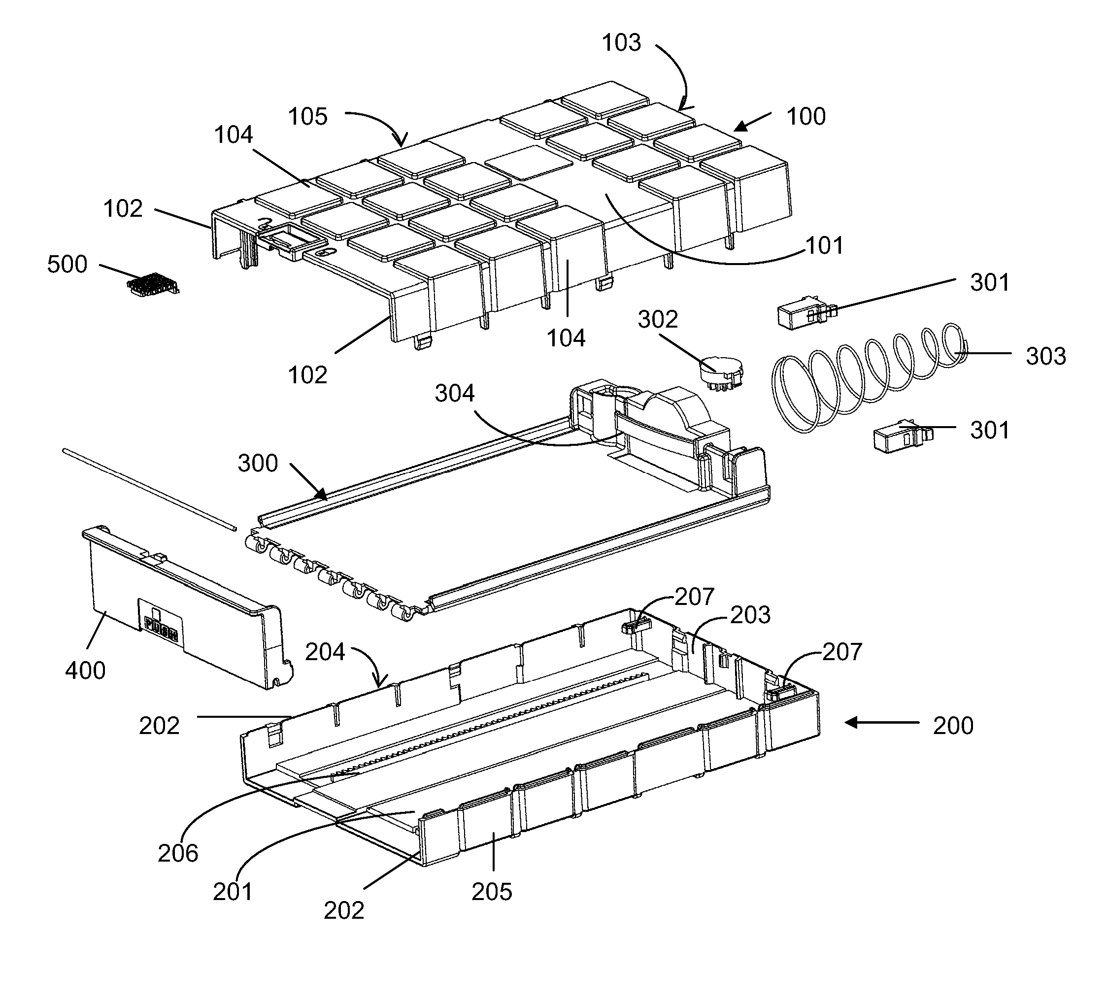
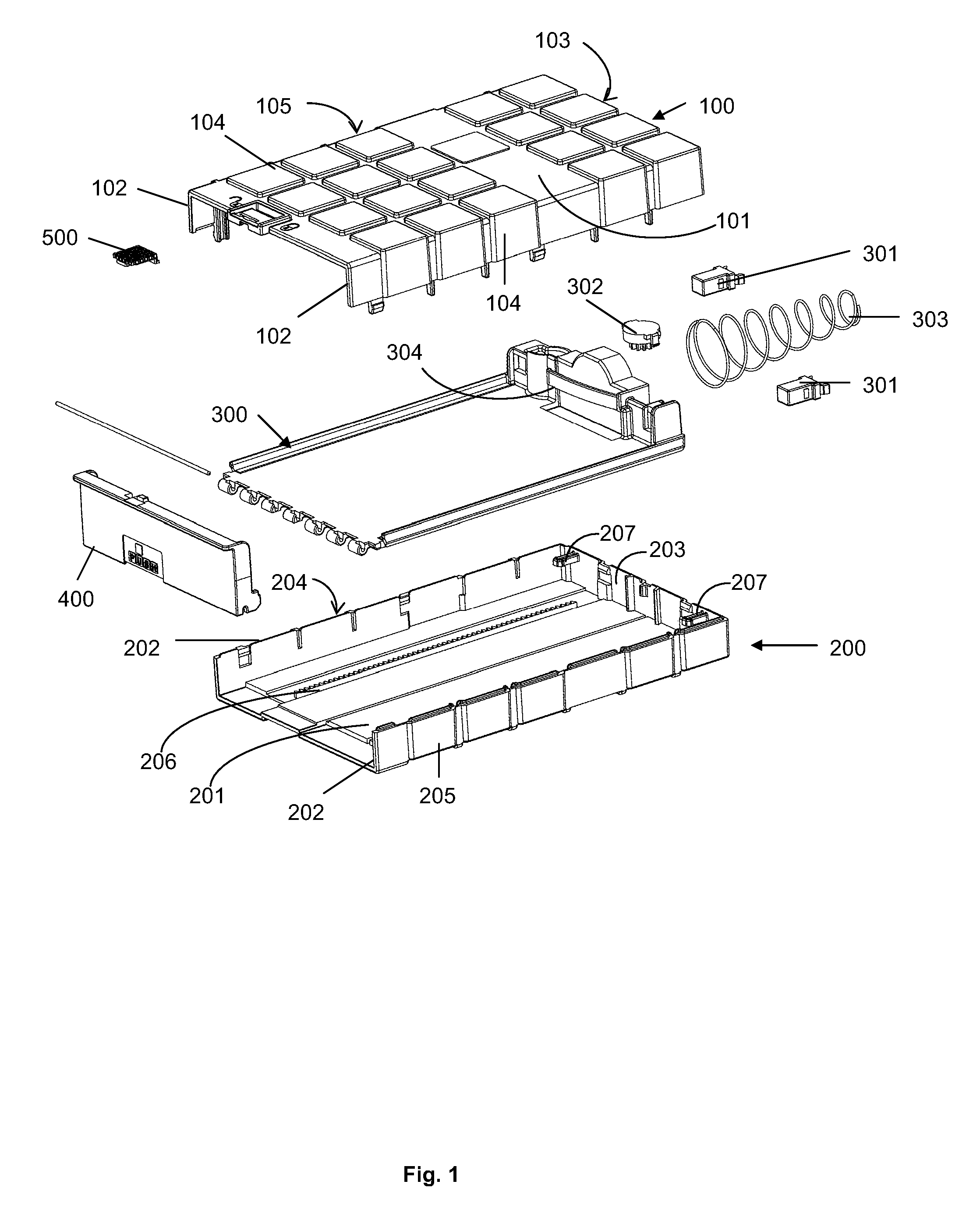
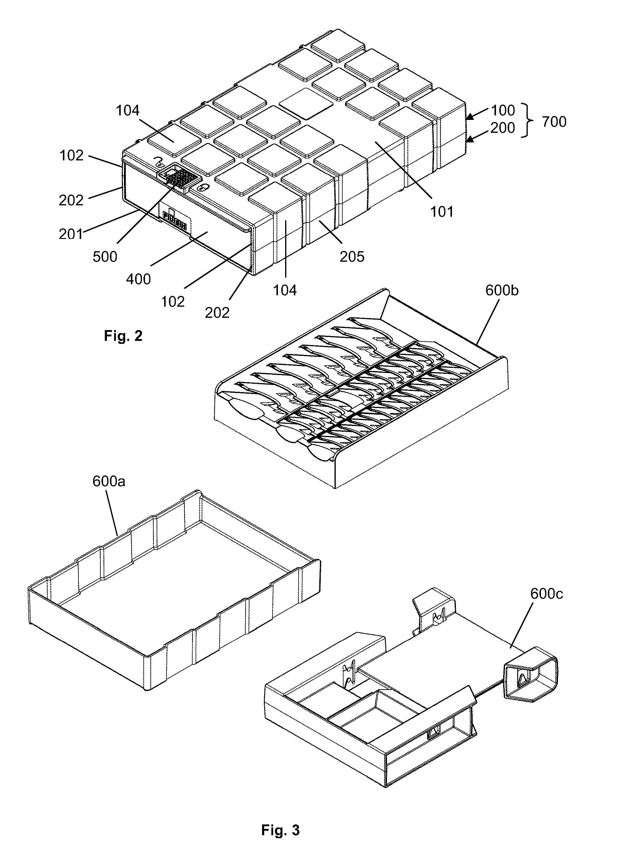
[0014]The container assembly of the present invention comprises a housing in the form of a right parallelepiped with five sides closed and the remaining side left open as an opening. In the preferred embodiment the container housing includes two separate housing members that, when assembled together, form the housing. In the preferred embodiment shown in the Figures the two housing members have the same size, i.e. the right parallelepiped of the housing is separated in the middle between the planes of the lower and upper walls of the container housing. Of course, other ways of dividing the housing into two parts are possible, for example the lateral side walls and the rear wall could extend from one of the upper and lower walls only, whereas the remaining of the upper and lower walls then would simply form a cover to be attached to the remaining housing part.

[0015]With reference to FIGS. 1 and 2 the container assembly of this embodiment comprises a first housing member 100, a second...


PUM

PropertyMeasurementUnit
sizeaaaaaaaaaa
resistanceaaaaaaaaaa
dimensionsaaaaaaaaaa

Abstract

A container assembly, comprising: a housing in the form of a right parallelepiped with one side left open, the closed sides being a lower main wall, two lateral walls, a rear wall, and an upper main wall, wherein a plurality of first raised portions of first predetermined shapes is formed on the upper main wall and a plurality of second raised portions of second predetermined shapes are formed at one of said lateral walls, while a plurality of second depressed portions of third predetermined shapes complementary to the second raised portions of said one first lateral wall are formed at the other of said two lateral walls, wherein a plurality of first depressed portions of fourth predetermined shapes complementary to the first predetermined shapes of the first raised portions are formed at the outer surface of the lower main wall, whereby a plurality of such container assemblies can be mutually engaged and thus stacked together by insertion the first raised portion into said corresponding first depressed portions and of the second raised portions into said corresponding second depressed portions formed at the outer surface of the housings of the container assemblies; a rack provided at the surface of the lower main wall in the inside of the housing and extending along a direction parallel to the longitudinal extension of said lateral walls; a pin that is provided at an inner surface of said rear wall; a base that is received and slideably moveable in the housing, said base being provided with a pin-engaging push-lock module and a reduction gear module having a gear in cogging engagement with the rack, wherein the pin-engaging module is engageable with the pin so as to secure the base in the housing, wherein the housing dimensions are adapted such that the inner space of the housing above the base corresponds to the size of a standard hard disk drive such that a standard hard disk drive placed on the base may be received in the housing in a manner free of play; a spring mechanism acting between a point on the inside of the walls within the housing and a rearward portion of the base so as to push the base to move outwards through the opening to project from the housing to the outside thereof, so that the base, when it is secured in the housing with the pin-engaging module engaging the pin, may be opened by pushing the base against the pin, thereby disengaging the push-lock module from the pin, whereupon the spring mechanism moves the base to the extended outward position against the resistance of the reduction gear module cogging with the rack; and a front cover assembled to a front end of the base so that, when the base is secured in the housing with the push-lock module in engagement with a pin, the front cover closes the opening of the housing.

Description

TECHNICAL FIELD[0001]The present invention relates to container assemblies, and in particular to a container assembly for storing peripheral computer memory devices, which allow to assemble or aggregate container assemblies to form a stacked multi-container assembly arrangement.DESCRIPTION OF RELATED ART[0002]With the progress and development of technology, computers have become an indispensable part of modern daily life. While computers offer convenience by providing basic operational functions for editing and storing of information, the related peripherals, such as hard disks, flash drives, flash cards and optical drives are also important accessories that assist computers in expanding their functions and storage capacity, providing external data storage media and maintaining efficient operation. These peripherals are typically not fixed components but are supplied individually as optional accessories which users choose according to their practical needs.[0003]For peripherals that...

Claims


Application Information

Patent Timeline
Patent Type & Authority Applications(United States)
IPC IPC(8): G11B33/04
CPCG11B33/02A47B87/007
Inventor BURGERHOFF, BURKHARD
Owner HELM BURGERHOFF BRIGITTE
Why Eureka
Try Eureka