Connector

a technology of connecting parts and connectors, applied in the direction of coupling device connection, securing/insulating coupling contact members, electrical devices, etc., can solve problems such as damage to contact parts, and achieve good interoperability

Active Publication Date: 2012-02-09
SUMITOMO WIRING SYST LTD
View PDF2 Cites 6 Cited by
  • Summary
  • Abstract
  • Description
  • Claims
  • Application Information

AI Technical Summary

Benefits of technology

[0007]The invention relates to a connector with at least one terminal fitting. A contact portion is formed near a front end of the terminal fitting for contacting a mating terminal. The connector also has a housing with a cavity and the terminal fitting can be inserted into the cavity from behind. A locking lance is cantilevered forward along an inner wall of the cavity. The locking lance normally is at a locking position where the locking lance can lock the terminal fitting in a retained state. However, the locking lance is resiliently deformable to an unlocking position where the locking lance is disengaged from the terminal fitting. A deformation space is formed in the housing to allow resilient deformation of the locking lance to the unlocking position. A front retainer is mounted to the housing from the front and includes a deformation restriction that projects back substantially along the inserting direction. The front retainer is movable between a restricting position and a retracted position. The deformation restriction enters the deformation space to restrict the deformation of the locking lance when the front

Problems solved by technology

This contact portion may be

Method used


Image

  • Connector
  • Connector
  • Connector

Examples


Embodiment Construction

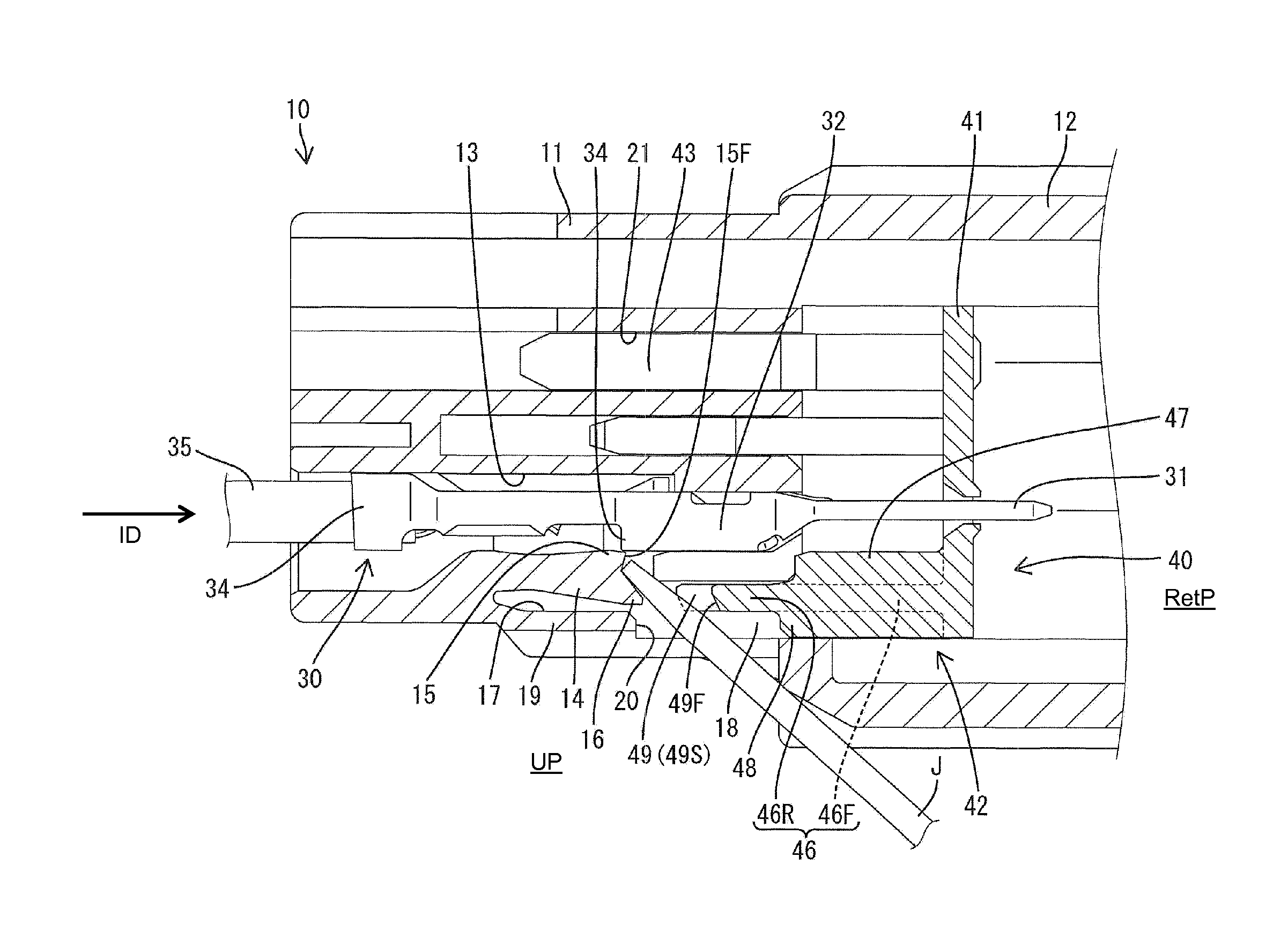
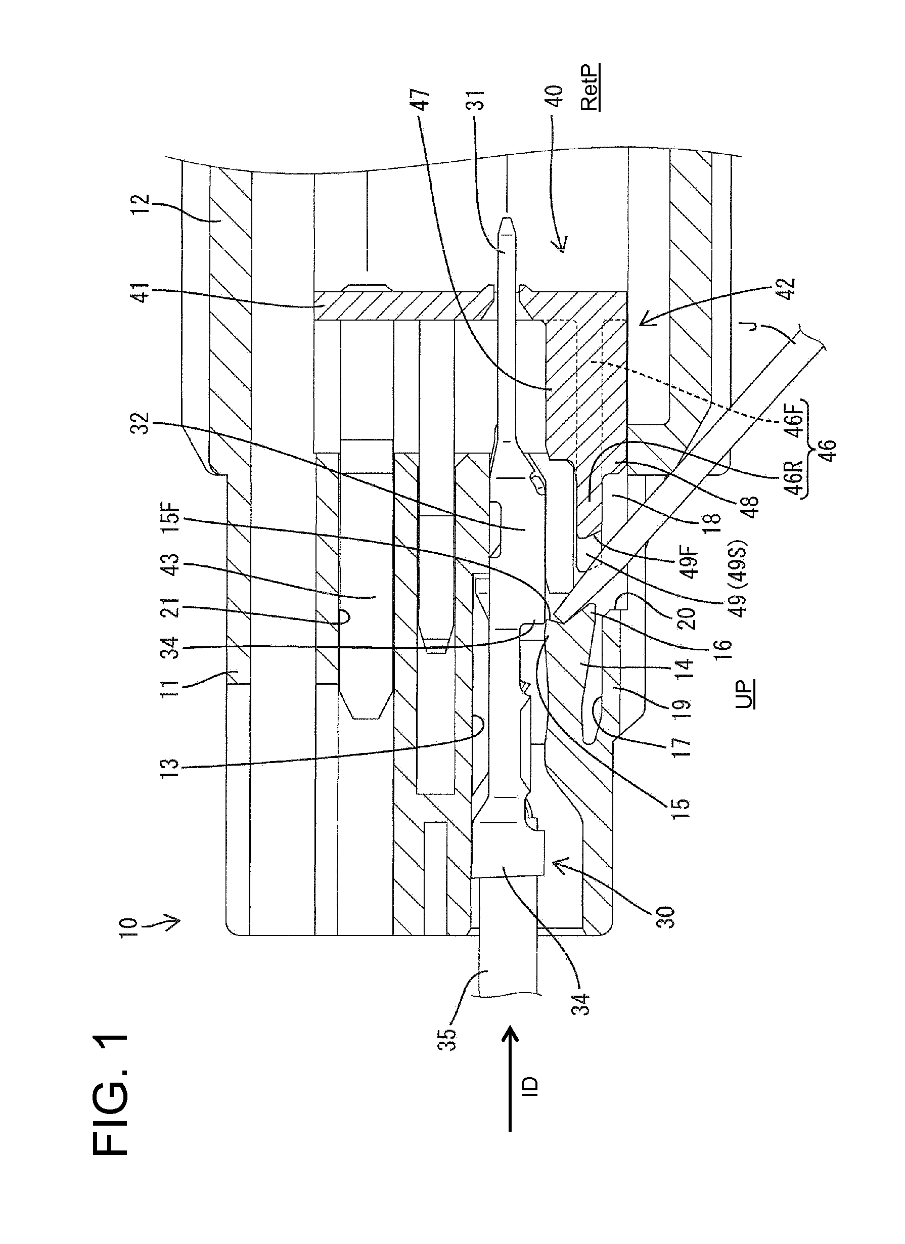
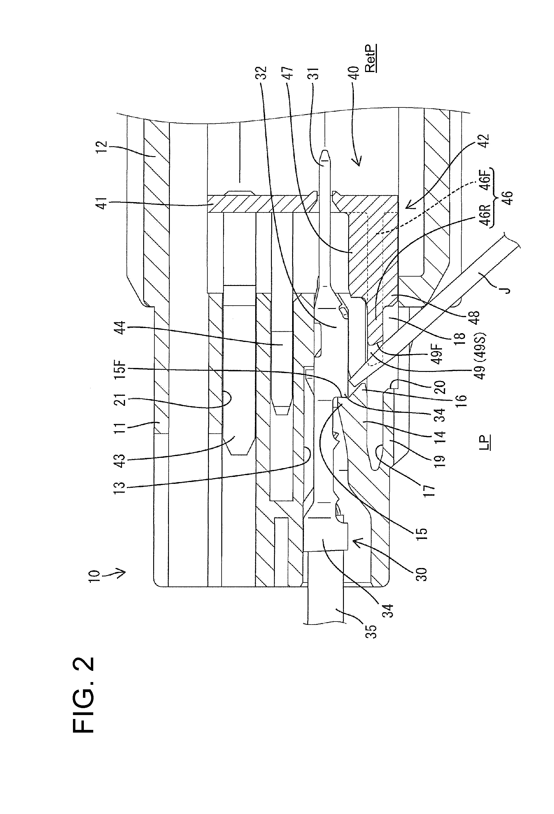
[0025]A connector in accordance with the invention includes a synthetic resin housing identified by the numeral 10 in FIGS. 1-7. The housing 10 is molded unitarily of synthetic resin and includes a substantially block-shaped terminal holding portion 11 and a rectangular tubular receptacle 12 that extends forward from the outer periphery of the front end of the terminal holding portion 11. Cavities 13 penetrate the terminal holding portion 11 in forward and backward directions at upper and lower stages and an insertion opening is defined at the rear end of each cavity 13 so that terminal fittings 30 can be inserted into the respective cavities from behind (left side in FIGS. 1 to 6) and along an insertion direction ID. A locking lance 14 is cantilevered forward along the lower wall of each cavity 13 in the lower stage. The front end of the locking lance 14 is behind the front end of the terminal holding portion 11 and behind the front end of the cavity 13.

[0026]A locking projection 1...


PUM


Abstract

A housing (10) is formed with jig insertion holes (20) penetrating through an outer wall (19) located at a side of deformation spaces (17) opposite to locking lances (14). Deformation restrictions (42) of a front retainer (40) are formed with guides (49) that are cut out to allow an unlocking jig inserted through the jig insertion hole (20) to reach the locking lance (14) when the front retainer (40) is at a retracted position and to position the unlocking jig in a width direction crossing both a resiliently deforming direction of the locking lances (14) and an inserting direction of terminal fittings (30) into cavities (13).

Description

BACKGROUND OF THE INVENTION[0001]1. Field of the Invention[0002]The invention relates to a connector.[0003]2. Description of the Related Art[0004]Japanese Unexamined Patent Publication No. 2005-166608 discloses a connector with a housing and a cavity formed in the housing. A locking lance is cantilevered forward along an inner wall of the cavity and a deformation space allows the locking lance to deform away from the cavity. A terminal fitting can be inserted into the cavity from behind and causes the locking lance to deflect into the deformation space. The locking lance then returns resiliently to engage the terminal fitting and hold the terminal fitting in the cavity. A front retainer is mounted to the housing after the terminal fitting is inserted and a deformation restricting portion of the front retainer enters the deformation space to prevent the locking lance from deforming out of engagement with the terminal fitting and to retain the terminal fitting reliably.[0005]The termi...

Claims


Application Information

Patent Timeline
IPC IPC(8): H01R13/627
CPCH01R13/4223H01R43/20H01R13/4364H01R13/42H01R13/639
Inventor TAKEDA, KAZUAKIUEZONO, KATSUYAHIRAISHI, TAKUMI
Owner SUMITOMO WIRING SYST LTD
Why Eureka
Try Eureka