
Titanium corotron and scorotron pins
- Summary
- Abstract
- Description
- Claims
- Application Information
AI Technical Summary
Benefits of technology
Problems solved by technology
Method used
Image

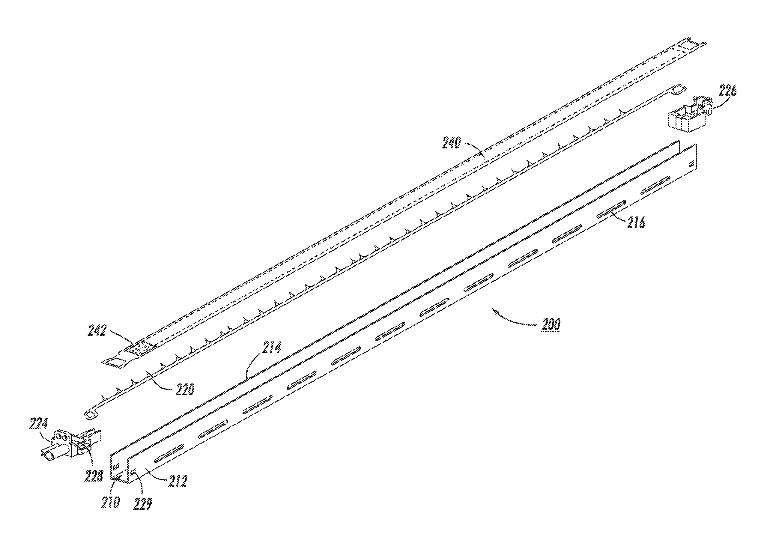
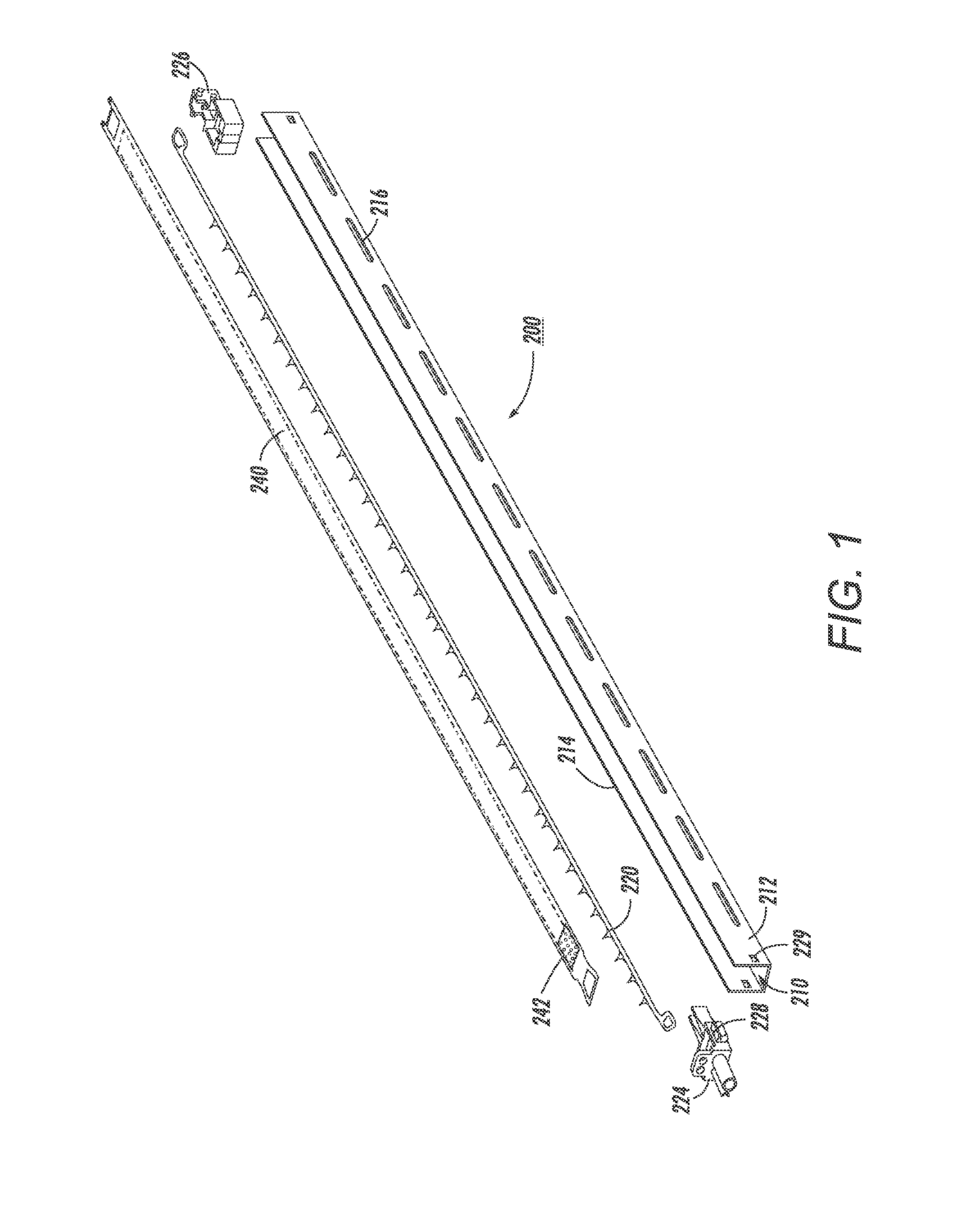
Examples
Embodiment Construction
[0019]While the present disclosure will hereinafter be described in connection with a preferred embodiment, it will be understood that it is not intended to limit the disclosure to that embodiment. On the contrary, it is intended to cover all alternatives, modifications and equivalents as may be included within the spirit and scope of the invention as defined by the appended claims.
[0020]For a general understanding of the features of the present disclosure, reference is made to the drawings. In the drawings, like reference numerals have been used throughout to designate identical elements.
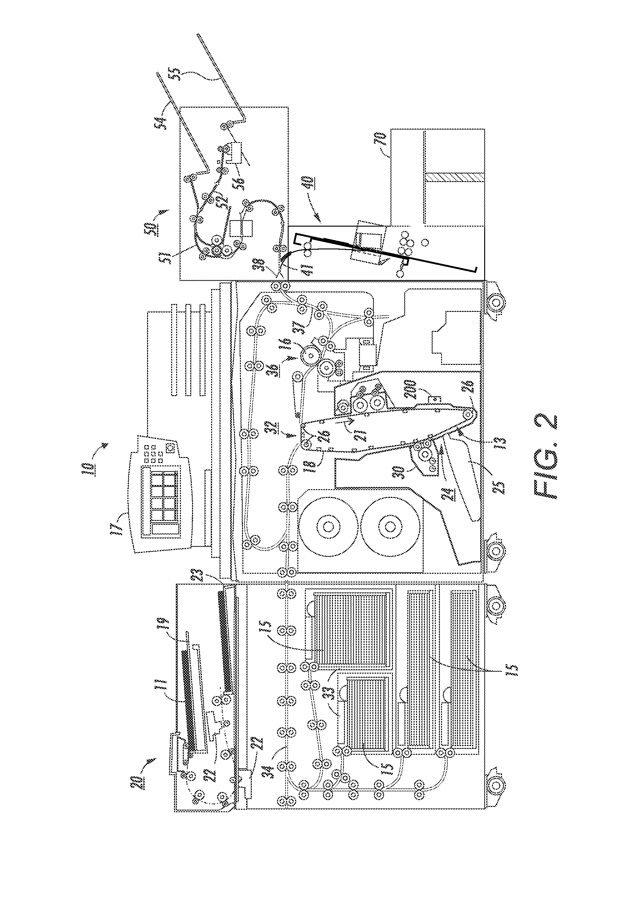
[0021]Referring to the FIG. 2 printer 10, as in other xerographic machines, and as is well known, an electronic document or an electronic or optical image of an original document or set of documents to be reproduced may be projected or scanned onto a charged surface 13 or a photoreceptor belt 18 to form an electrostatic latent image. Optionally, an automatic document feeder 20 (ADF) may be provided...
PUM
 Abstract
Description
Claims
Application Information