

Automatic cover-opening device
a cover-opening device and automatic technology, applied in the direction of door/window fittings, wing accessories, wing arrangements, etc., can solve the problems of limited use inconvenient use, limited application of conventional cover-opening devices, etc., to achieve convenient use, convenient use, and versatile
- Summary
- Abstract
- Description
- Claims
- Application Information
AI Technical Summary
Benefits of technology
Problems solved by technology
Method used
Image

Examples
second embodiment
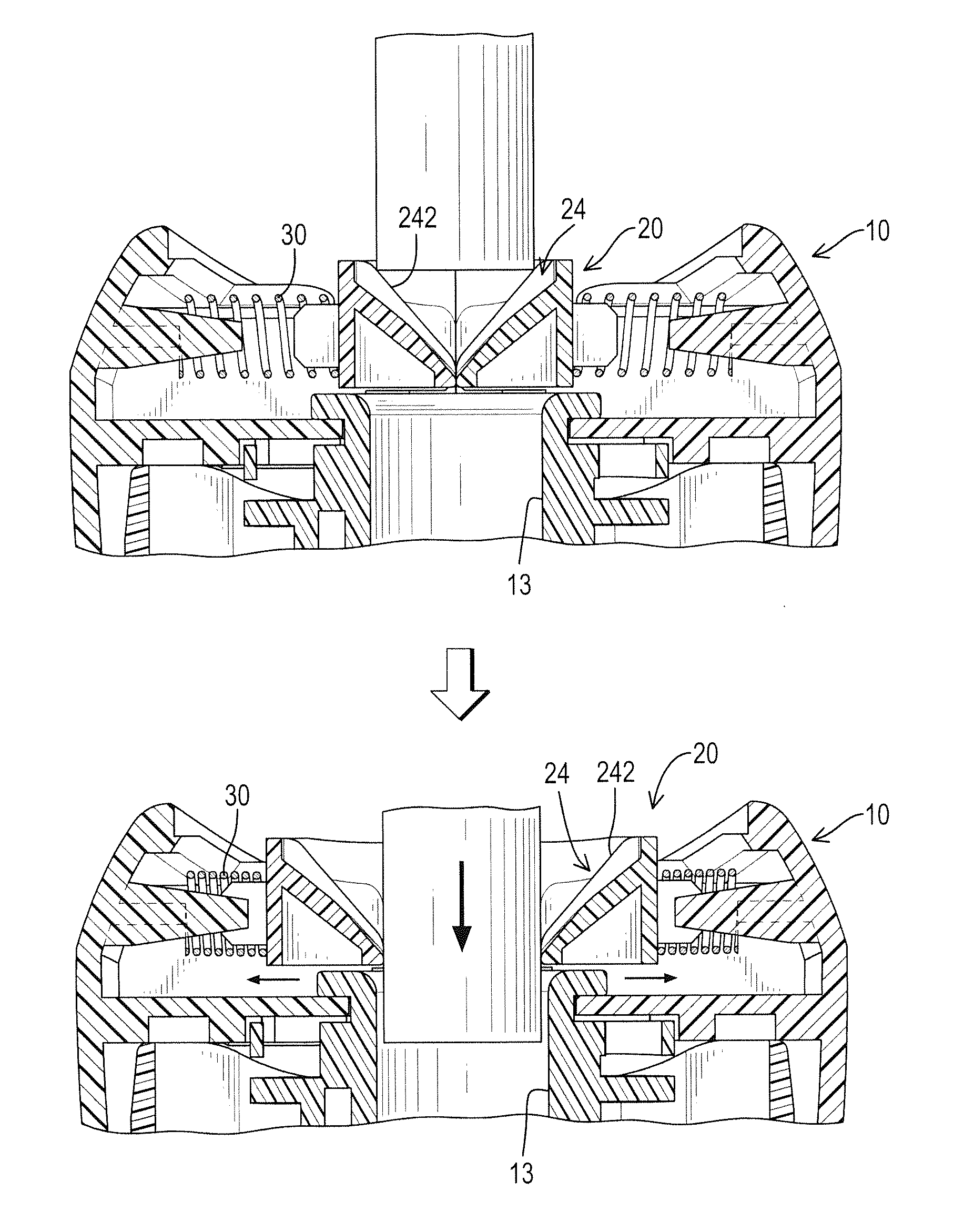
[0028]With reference to FIGS. 5 and 6, an automatic cover-opening device in accordance with the present invention, the insertion hole 13A and the rail 16A are disposed on the cutter assembly 15A in the body 10A, and the rail 16A comprises two rail tabs 162A in a substantially trapezoid shape. Each rail tab 162A has two inclined surfaces 164 formed respectively on two sides of the rail tab 162A, and each cover panel 20A has a recess 22A formed in a top surface of the cover panel 20A and having an inclined bottom surface, and each cover panel 20A further has a wing 26 formed on and protruding from a side of the cover panel 20A and moveably abutting the rail tabs 162A. The guiding segment 24A on each cover panel 20A comprises a groove defined in the inclined bottom surface of the recess 22A. Two guiding edges 242A are respectively formed on two sides of the groove. In addition, the springs 30A of the recoil mechanism are both disposed in an inclined manner. With reference to FIG. 7, wh...
third embodiment
[0029]With reference to FIGS. 8 and 9, an automatic cover-opening device in accordance with the present invention, the base 12B is mounted on the waste casing 11B, and the insertion hole 13B is defined in the base 12B. Two cover panels 20B are pivotally mounted on a pivotal axle 18 on the body 10B. The rail 16B comprises a curved rail rib 162B formed on a top surface of the base 12B and having a center at the pivotal axle 18. The coil mechanism comprises a torque spring 30B having two ends abutting the two cover panels 20B. Each cover panel 20B has a rail bracket 28 formed on and protruding from an end of the cover panel 20B and mounted slidably over the rail rib 162B. Each cover panel 20B has a recess 22B defined in a top surface of the cover panel 20B and having a flat bottom surface. The guiding segment 24B of each cover panel 20B comprises two triangular guiding tabs, and each guiding tab has an inclined guiding edge 242B.
[0030]With reference to FIG. 10, when a pencil is inserte...
fourth embodiment
[0031]With reference to FIGS. 11 to 13, an automatic cover-opening device in accordance with the present invention, three moveable cover panels 20C are implemented in the body 10C to close the insertion hole 13C. The cover panels 20C are fan-shaped in cross section and are formed in combination as a complete round cover to close the insertion hole 13C. The insertion hole 13C is defined in the cutter assembly 15C. The guiding segment 24C on each cover panel 20C comprises an abutting rib with a thick top and a thin bottom. The rail 16C in the body 10C comprises three sets of rail ribs 162C radially arranged around the insertion hole 13C and is disposed on a top surface of the cutter assembly 15C. Each set of rail ribs 162C comprises two rail ribs 162C parallel with each other. Each cover panel 20C has a rail channel 29 defined in a bottom of the cover panel 20C and holds one of the sets of rail ribs 162C inside the rail channel 29. Accordingly, each cover panel 20C is moveable relativ...
PUM
 Abstract
Description
Claims
Application Information